- SMT Assembly, BGA Assembly, Through hole Assembly, Mixed Assembly
- PCB assembly or Box build assembly service delivers a PCBA or a complete electronics assembly in a box
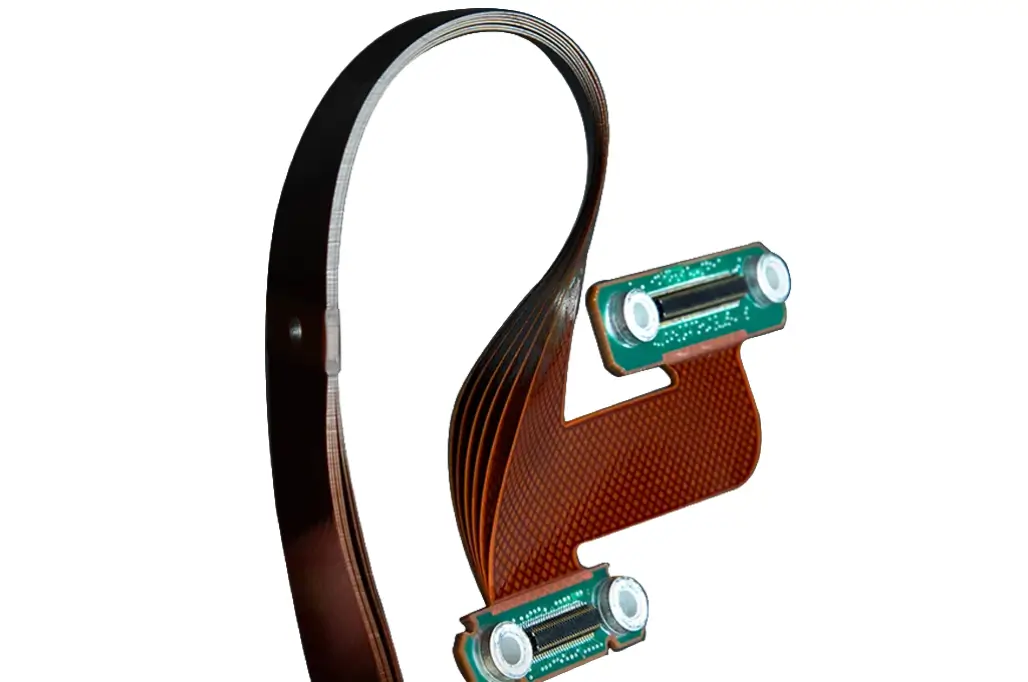
Top-Tier Rigid Flex PCB Assembly & Comprehensive Rigid Flex Assembly Solutions
Rigid Flex PCB Assembly Capabilities & Advanced Technologies
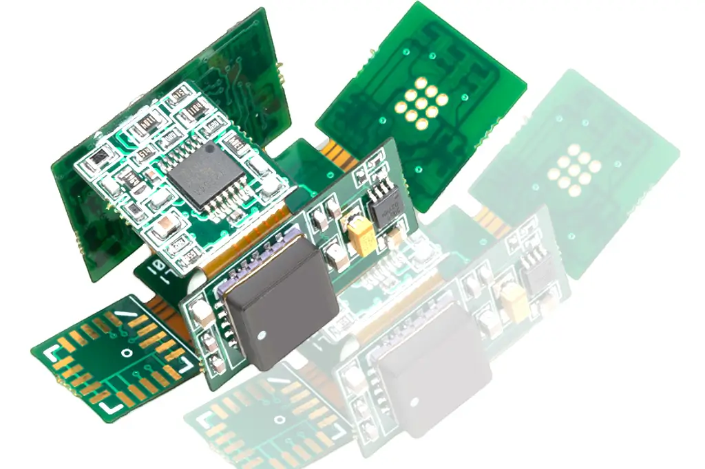
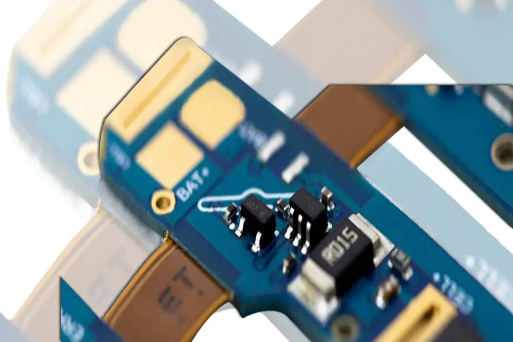
Our rigid flex PCB assembly capabilities cover a full range of advanced processes to meet complex electronic project needs. We specialize in SMT assembly (supporting 0201 chip components and 0.4mm pitch BGAs), through-hole assembly, flip chip bonding, and selective soldering for precise joint formation. Quality control is enhanced by in-circuit testing (ICT), flying probe testing, X-ray inspection for hidden solder joints (e.g., BGA packages), and automatic optical inspection (AOI) with ±0.02mm accuracy. We also offer conformal coating (Acrylic, Parylene) to protect assemblies from moisture and dust, and press fit technology for reliable component connections. Our state-of-the-art equipment and 15+ years of engineering experience ensure we handle high-layer count rigid-flex designs (up to 16 layers) with zero delamination risks.
Key Considerations for Rigid Flex Assembly Process
Rigid Flex Assembly: Key Material Specifications
Rigid flex assembly relies on high-quality materials to ensure structural integrity and performance. We use no-flow prepreg as the core bonding material, which flows only to the rigid-flex transition edge without spreading onto flexible sections—preventing flex layer damage. Flexible layers are made of polyimide films (DuPont Kapton) with excellent thermal resistance (-40°C to 125°C) and mechanical flexibility, while rigid sections use FR-4 substrates with 1oz-4oz copper foil for stability. All materials meet IPC-4201 and RoHS standards, with dielectric strength ≥20 kV/mm and insulation resistance ≥10¹² Ω to ensure electrical reliability.
Pre-Bake Specifications for Rigid Flex PCB Assembly
Pre-baking is critical for rigid flex PCB assembly to eliminate moisture from hydroscopic polyimide materials (which absorb 2-3% water by weight). Our standard pre-bake process follows industry guidelines: 120°C temperature with duration adjusted by design complexity—2 hours for basic single-layer flex sections, 4-6 hours for multi-layer designs (4-8 layers), and up to 10 hours for high-layer count (10+ layers) or stiffener-rich assemblies. For boards manufactured and assembled in-house (no transit time), pre-bake is optimized or omitted to streamline lead times without compromising quality. Post-baking, boards are stored in low-humidity environments (<40% RH) to prevent moisture reabsorption.
Array Design & Handling for Rigid Flex Assembly
Rigid flex assemblies are supplied in arrays to ensure stability during processing. Our recommended array designs include mouse bites for rigid sections (facilitating clean separation) and tabs for flexible sections (preserving flex layer integrity). V-scoring is available for rigid regions with FR-4 stiffeners (minimum 1.6mm thickness) but avoided for flex-only areas to prevent rough edges. Array dimensions are optimized for our production line (maximum 600x1200mm) to maximize efficiency, and we provide detailed array design guidelines to clients for seamless integration with their assembly process.
Part Retention Solutions for Rigid Flex PCB Assembly
Part retention in rigid flex PCB assembly is achieved through tailored solutions based on design requirements. Mouse bites (3mm spacing, 1mm depth) are used for rigid section breakaways, while tabs (5mm width, 2mm length) secure flexible sections during assembly. For complex designs, we integrate temporary stiffeners at flex-rigid transitions to prevent deformation during SMT placement. Post-assembly, parts are separated using precision cutting tools—laser cutting for flex sections (minimizing edge damage) and mechanical cutting for rigid regions—ensuring clean, burr-free edges that meet dimensional tolerances (±0.1mm).
Rigid Flex PCB Assembly Guidelines & Best Practices
To ensure optimal reliability of rigid flex PCB assemblies, we follow strict guidelines: Components near flex sections must be supported by FR-4 stiffeners (minimum 1.0mm thickness) to distribute stress. SMT components are placed on one side of flex layers, while through-hole components are mounted on rigid sections or over stiffeners. Stiffeners are applied on the opposite side of SMT components and the same side as through-hole parts to balance mechanical stability. We avoid component placement within 2mm of flex-rigid transition lines to prevent vibration-induced damage. All assemblies undergo thermal shock testing (-55°C to 125°C, 100 cycles) and humidity testing (85°C/85% RH, 500 hours) to validate performance in harsh environments.
Turn-Key Rigid Flex Assembly Component Procurement Services
Our turn-key rigid flex assembly services include end-to-end component procurement from authorized distributors (Digi-Key, Mouser, Avnet) to ensure authenticity and quality. We handle full BOM management—verifying part numbers, checking stock availability, and sourcing alternatives for obsolete components—eliminating delays for clients. For those preferring partial or consigned assembly, we accept customer-supplied components with strict incoming inspection (visual check, solderability testing, and dimensional verification). Our procurement team leverages volume purchasing power to secure competitive pricing, passing savings to clients while maintaining traceability (material certificates provided upon request). We support small-batch (1-100 units) and pre-production (100-500 units) orders with quick procurement lead times (3-5 days for standard components).
Rigid flex PCB Assembly Capabilities
We pride ourselves on the ability to take on complex jobs — from fabrication to assembly — all under one roof with state-of-the-art technology, including a new selective soldering machine.
Our engineering team uses best practices for flex and rigid-flex pcb assembly, and our operators understand how to properly assemble flex circuits to avoid delamination.
- Surface mount technology (SMT)
- Through hole
- Flip chip
- In-circuit testing (ICT) and flying probe testing
- X-ray inspection
- Press fit
- Conformal coating
- Automatic Optical Inspection (AOI)
- Selective Soldering
Considering of rigid-flex assembly
Rigid-flex PCBs are assembled similarly to rigid boards. However, there are a few differences.
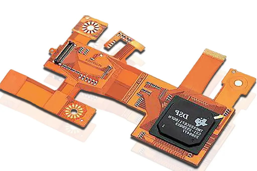
Rigid-flex materials
Rigid-flex boards are fabricated using the same materials that hardboard and flexible boards are built with. The only difference is that they are built using no-flow prepreg. No flow prepreg is essential in rigid-flex manufacturing, as it flows up to the edge of the rigid-flex transition area without flowing out onto the flexible sections of the board.
Baking rigid-flex PCBs
Generally, the materials used in these boards (flex layers, coverlays, and bondplies) absorb water from their environment. The absorbed water will greatly expand during the thermal excursion of assembly and will damage the board. Hence, it is necessary to bake these boards prior to the assembly process.
Rigid-flex arrays
Generally, fabricators and assembly houses prefer to have rigid-flex circuits supplied in arrays. This holds the boards stable during assembly. Once the assembly process is completed, the boards are removed from the arrays .Always contact your manufacturer to know more about the array requirements.
Part Retention Within The Assembly Array
The most common solution for breakaways in rigid-flex PCBs are mouse bites – similar to standard rigid PCBs. For flexible circuit designs the common solutions are tabs. Tabs are the small uncut sections or the part outline.
V-scoring may also be used for rigid-flex designs. A post assembly cutting system will be required to finish the V-Score cut and allow the parts to be separated from the array. V-Scoring will leave the centrally located flex layers uncut. V-Score is generally not used on flex only designs as the cutting process leaves an undesirable rough edge finish. The flex design must also have FR4 stiffeners thick enough to accommodate the capabilities of the V-Score process.
Rigid-flex assembly notes
Follow these guidelines:
- If components are placed close to the flex section, have stiffeners around the flex area.
- If the stiffeners are used for mechanical reasons, try to place components over the stiffener or rigid area.
- Flex circuits typically have SMT components on one only side of the board.
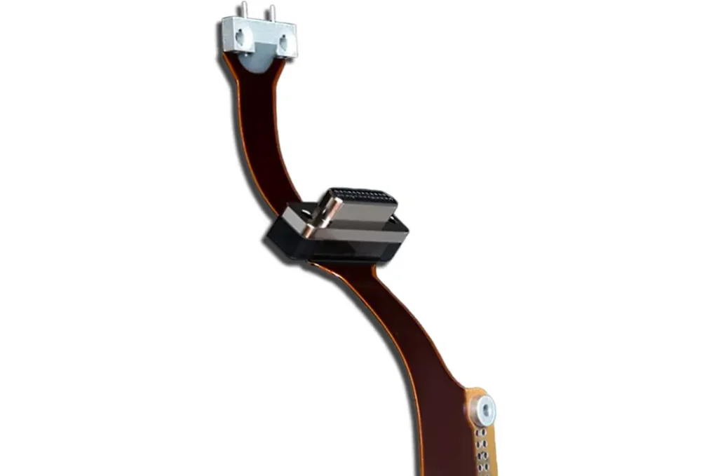
- Rigid-flex circuits are stiffened along most of their surface, with relatively small areas left unstiffened – the hinges or flexible arms.
- Apply stiffeners on the opposite side of SMT components and on the same side for through-hole components.
- The pre-bake cycle eliminates any moisture retained in the board and allows for improved assembly yields and reliability. However, if boards are assembled immediately after manufacturing, there is no need for pre-bake. Since Benchuang Electronics manufactures and assembles under one roof, we eliminate the need for pre-bake.
Rigid flex PCB Assembly Pre-Bake Specifications
Flexible Polyimide materials used in the fabrication of flexible and rigid-flex circuits are hydroscopic up to 2-3% by weight and as such require a thorough pre-bake to eliminate all moisture prior to any assembly process. This is an inherent property of the materials and is independent of the manufacturer and or the brand of polyimide materials used.
The industry accepted standard is to pre-bake all flex circuits immediately prior to assembly and without exceptions, even if the product has recently been received from the supplier in a vacuum sealed package. Baking the product prior to packaging does not eliminate the need for pre-baking prior to assembly.
Failure to remove all moisture is the primary cause of coverlay delamination, layer to layer delamination, and stiffener delamination. The root cause being the conversion of the entrapped moisture to steam at assembly re-flow temperatures. The expansion of the steam results in the delamination.
It is recommended that the flex PCB parts be pre-baked at 120°C. The duration of the pre-bake will vary depending upon the design of the specific parts. Layer count, stiffeners, and flex circuit construction are factors that will increase the pre-bake time required. Pre-bake times will vary from minimum of 2 hours up to 10 hours for high layer count flex circuit designs.
Rigid flex PCB Component Procurement
Benchuang Electronics offers full turn-key capabilities, which means we will take care of procuring all materials and components. A turn-key solution eliminates delays and allows for peace of mind knowing your PCB is in the hands of our expert engineers from start to finish. We also offer partial and consigned assembly services if you’d prefer to secure the components and materials yourself.
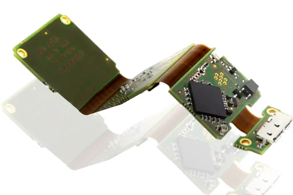
Rigid-flex boards have effectively reduced a product’s size without compromising the quality. They can solve contact and intense heat problems caused by harnesses and connectors, drastically improving the reliability of devices.
Get started with Printed Circuit Assembly
- Box build assembly
- Flex pcb assembly
- Rigid flex assembly
- SMT Assembly, BGA Assembly, Through hole Assembly, Mixed Assembly