
What Is DFM Check in HDI PCB? Essential Practices for Reliable High-Density Interconnect Circuit Boards
HDI (High-Density Interconnect) PCBs are the backbone of modern electronics, powering devices from smartphones to aerospace systems with their compact design, fine traces, and microvias. Design for Manufacturability (DFM) check in HDI PCB is a systematic evaluation process that ensures the PCB design aligns with manufacturing capabilities, addressing unique challenges of high component density, tight spacing, and complex layer structures. This article details core DFM check elements, critical considerations, and actionable processes to optimize HDI PCB production.
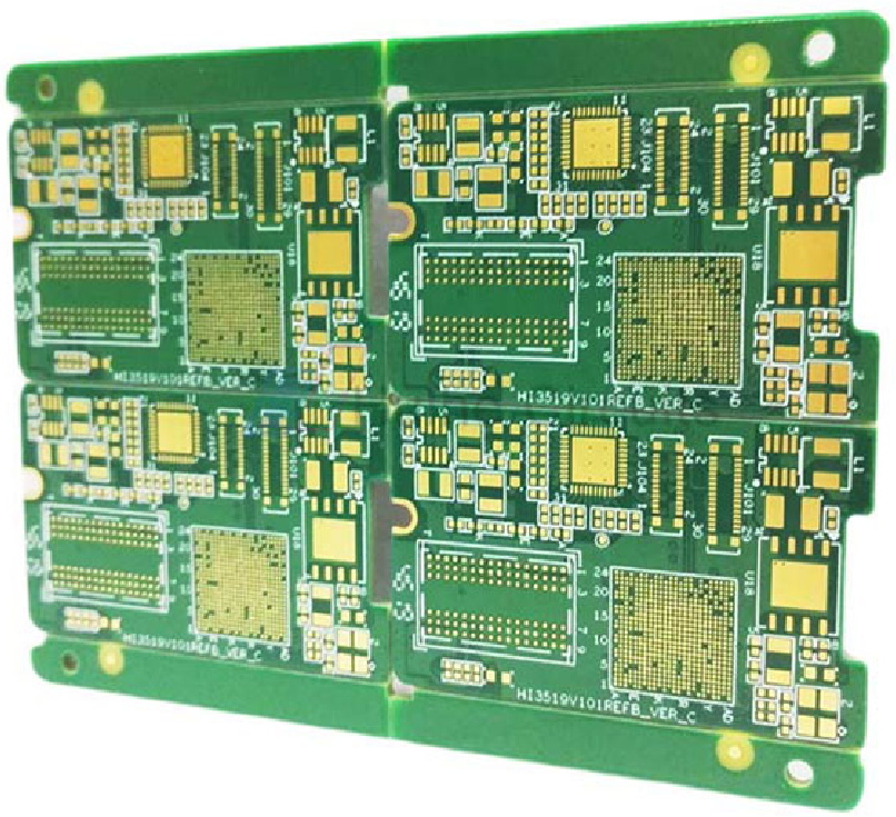
Learn more about : How to Design HDI Microvia PCB
Why HDI DFM Is Critical for PCB Manufacturing
HDI PCBs demand precision due to microvias, thin dielectrics, and dense component placement, making DFM checks non-negotiable for successful production. Below are the key benefits of rigorous DFM checks for HDI circuit boards:
Reduces Defects in HDI PCB Production
HDI PCBs face inherent manufacturing risks such as trace shorts, via voids, and layer misalignment. DFM checks identify design flaws early, including inadequate annular rings, improper microvia aspect ratios, and insufficient trace spacing. By adhering to IPC-2221 and IPC-6012 standards, DFM checks minimize defects like undercuts in fine traces, poor hole quality in laser-drilled microvias, and thermal failures from inadequate material selection. For example, verifying a minimum annular ring of 0.05 mm (2 mil) per IPC Class 3 requirements prevents mechanical and environmental failures in critical applications like defense and avionics.
Increases Yield of High-Density Circuit Boards
DFM checks align HDI PCB designs with fabrication capabilities, reducing the likelihood of scrapped boards. High component density and tight layer registration in HDI PCBs often lead to yield loss without proper DFM. By optimizing via structures, trace widths, and material compatibility, DFM checks boost yield rates—industry data shows that HDI PCB designs with comprehensive DFM checks achieve 15-25% higher yields compared to non-optimized designs. This is particularly impactful for multilayer PCBs and rigid flex PCBs, where rework costs are significantly higher.
Saves Time & Cost in HDI PCB Development
Without DFM checks, HDI PCB production faces costly delays from redesigns, re-spins, and manufacturing bottlenecks. DFM checks eliminate last-minute design modifications by addressing issues like non-standard component selection, complex stack-ups, and unmanufacturable via configurations early in the process. For instance, choosing staggered vias over stacked vias reduces planarization steps, cutting production time by 10-15% and lowering material costs. Additionally, DFM checks reduce soft costs such as engineering rework, supplier communications, and test failures, which can account for 30% of total project expenses.
Enhances Performance of HDI Circuit Boards
DFM checks optimize HDI PCB performance by addressing signal integrity, thermal management, and mechanical reliability. High-density designs are prone to crosstalk, impedance mismatches, and thermal sensitivity—DFM checks mitigate these issues through controlled impedance routing, proper ground plane placement, and thermal via integration. For RF PCBs and high-speed applications, DFM checks ensure trace uniformity and dielectric consistency, maintaining signal integrity and reducing transmission delays. Materials with Tg ≥200°C selected via DFM checks enhance thermal reliability, critical for HDI PCBs in harsh environments.
Key DFM Considerations for HDI PCB Design
Microvias in HDI PCB
Microvias (diameter ≤6 mil) are defining features of HDI PCBs, enabling dense interconnections between layers. DFM checks for microvias focus on:
- Aspect Ratio: Maintain a maximum aspect ratio of 0.75:1 (drill depth to diameter) for reliable copper plating, per industry standards. For example, a 3-mil dielectric requires a 3.9-4 mil drill size to meet this ratio.
- Drilling Method: Laser drilling is mandatory for microvias <6 mil, as mechanical drilling lacks the precision and strength for small diameters. Laser drilling ensures controlled depth for blind vias and buried vias.
- Material Compatibility: Select laser-drillable materials (e.g., PTFE, aramid fiber, or modified FR-4) to prevent uneven ablation and poor hole quality. Uniform dielectric thickness minimizes resin residue and ensures consistent plating.
- Void Prevention: Stacked microvias require filling with non-conductive epoxy to avoid voids, while staggered microvias eliminate planarization needs and reduce void risks.
Layer Stackup Optimization
Layer stackup directly impacts HDI PCB manufacturability, signal integrity, and cost. DFM checks for stackup include:
- Symmetry: Symmetrical layer configurations prevent warping during lamination, especially for multilayer PCBs with odd layer counts.
- Sequential Lamination: Use sequential build-up (SBU) processes for complex HDI designs, enabling blind/buried vias and microvia integration. Limit lamination cycles to 3 for reliability.
- Material Selection: Choose dielectrics with compatible CTE (Coefficient of Thermal Expansion) to avoid delamination. Non-reinforced dielectrics (e.g., polyimide, epoxy liquid) down to 1 mil thickness support thin HDI structures but require thermal control.
- Impedance Planning: Align stackup with controlled impedance requirements, ensuring consistent trace-to-plane spacing for signal layers in RF PCBs and high-speed HDI circuit boards.
Trace/Space Requirements
Fine traces and tight spacing are hallmarks of HDI PCBs, requiring strict DFM adherence to avoid shorts and signal degradation:
- Minimum Dimensions: Follow IPC-2221 standards for trace width and spacing—typical minimums are 50 microns (2 mil) for traces and spacing, with advanced processes supporting 25 microns (1 mil) for ultra-dense designs.
- Etch Uniformity: Use thin copper weights (½ oz, ⅓ oz, or ¼ oz) to minimize undercuts, ensuring rectangular trace profiles instead of trapezoidal shapes.
- Contamination Control: Trace widths ≤1 mil are vulnerable to dust and debris, requiring Class 100 cleanroom manufacturing per ISO 14644-1 to maintain trace integrity.
- Copper-to-Edge Spacing: Maintain a minimum of 0.010″ (254 microns) between copper features and the board edge to prevent mechanical stress and signal leakage.
Via-in-Pad Design
Via-in-pad technology maximizes routing density in HDI PCBs by placing microvias directly within component pads, but requires careful DFM checks:
- Filling Requirements: Vias-in-pad must be filled with conductive or non-conductive epoxy and plated over to ensure planarity for SMT components. This adds manufacturing steps but eliminates signal loss from dogbone routing.
- Thermal Management: Filled vias-in-pad improve heat dissipation, critical for high-power components in HDI PCBs and flexible printed circuits.
- Manufacturability Checks: Verify fabricator capabilities for via-in-pad processes, including drilling precision, epoxy filling, and plating uniformity to avoid solder defects.
Impedance Control
Impedance control is critical for HDI PCBs in high-speed and RF applications, with DFM checks focusing on:
- Consistent Trace Geometry: Maintain uniform trace width and spacing across signal layers, adhering to impedance profiles (e.g., 50Ω, 100Ω differential) specified in the design.
- Material Properties: Select dielectrics with stable Dk (dielectric constant) values to prevent impedance variations. For example, Rogers RO4003 and RO4350 are ideal for RF PCBs due to low Dk drift.
- Layer Registration: Precise layer alignment (±0.005″ tolerance) ensures consistent trace-to-plane distances, critical for controlled impedance in multilayer HDI PCBs.
- Test Validation: Include impedance test coupons in the design to verify compliance with IPC-6012 Class 3 standards during production.
Component Density & Placement
High component density in HDI PCBs requires DFM checks to balance functionality and manufacturability:
- Pitch Compatibility: Ensure component pitch (e.g., BGA fine pitch ≤0.3mm) aligns with microvia size and routing capabilities. Staggered vias accommodate fine-pitch components better than stacked vias.
- Thermal Clearance: Provide adequate spacing between high-power components and heat-sensitive parts (e.g., capacitors) to prevent thermal damage. Thermal vias placed near heat-generating components improve dissipation.
- Assembly Access: Avoid component overcrowding to enable automated optical inspection (AOI) and flying probe testing. Maintain clearances for solder joints and test points per IPC-7351 standards.
Drill to Copper Clearance
Drill to copper clearance prevents short circuits and ensures reliable connections in HDI PCBs:
- Minimum Clearance: Follow IPC guidelines for finished hole-to-copper clearance, calculated as drill-to-copper clearance plus twice the plating thickness. For a 6 mil drill and 1 mil plating, the minimum finished clearance is 8 mil.
- Hole Spacing: Avoid touching or closely spaced holes, which can weaken the PCB structure and cause lamination issues. Minimum hole spacing is typically 0.020″ (508 microns) for microvias.
- Drill Precision: Laser drilling ensures hole positioning accuracy (±0.002″) for tight drill-to-copper clearance requirements in high-density designs.
HDI DFM Check Process: Step-by-Step Implementation
Collaborate Early with Manufacturers
Engage fabrication partners during the initial design phase to:
- Confirm capabilities for microvia drilling, sequential lamination, and via-in-pad processes.
- Obtain DFM guidelines specific to their equipment, including minimum trace width, via size, and material compatibility.
- Align stackup design with their lamination cycles and layer registration capabilities to avoid costly reworks.
Implement DFM Rules in Design Software
Integrate DFM constraints into ECAD tools (e.g., Altium Designer, Cadence Allegro) to automate checks:
- Set minimum trace width/spacing, annular ring size, and drill-to-copper clearance per manufacturer guidelines.
- Configure impedance control rules based on stackup data and IPC-2221 standards.
- Enable via structure checks (aspect ratio, type, placement) to prevent non-manufacturable configurations.
Perform Comprehensive DFM Check
Conduct a multi-stage DFM review covering:
- Layer Stackup: Verify symmetry, material compatibility, and lamination cycle feasibility.
- Via Design: Check microvia aspect ratio, filling requirements, and placement (stacked vs. staggered).
- Trace & Spacing: Ensure compliance with IPC standards and manufacturer capabilities.
- Component Placement: Validate pitch compatibility, thermal clearance, and assembly access.
- Manufacturing Files: Review Gerber/ODB++/IPC-2581 files for completeness and accuracy.
Generate Production-Ready Files
Submit complete documentation to manufacturers, including:
- Gerber files (layers, solder mask, silkscreen)
- NC drill files with hole sizes and locations
- IPC-356A netlist for electrical verification
- Component placement (pick-and-place) files
- Stackup diagrams with material specifications and thicknesses
- Test plans (AOI, X-ray, flying probe, functional testing)
HDI DFM Check FAQs
What Is the Difference Between HDI PCB and Standard PCB DFM Checks?
HDI PCB DFM checks focus on microvia design (aspect ratio, drilling method), sequential lamination, and fine-pitch component compatibility—areas less critical in standard PCBs. Standard PCB DFM checks prioritize through-hole vias and larger trace widths, while HDI requires precision for features ≤6 mil and tight layer registration.
How Does DFM Check Impact HDI PCB Cost?
DFM checks reduce costs by minimizing re-spins (saving 20-30% of project expenses), increasing yield (lowering scrap rates), and optimizing manufacturing processes (e.g., avoiding expensive planarization for stacked vias). While initial DFM implementation takes time, the long-term cost savings are significant for high-volume HDI PCB production.
What IPC Standards Govern HDI PCB DFM Checks?
Key IPC standards include:
- IPC-2221: Generic Standard on Printed Board Design (trace width, spacing, clearance)
- IPC-6012: Qualification and Performance Specification for Rigid Printed Boards (reliability requirements)
- IPC-4104: Specification for Base Materials for Rigid Printed Boards (material standards)
- IPC-2581: Generic Requirements for Printed Board Assembly Products Manufacturing Description Data and Transfer Methodology (file format)
Can DFM Checks Be Applied to Flexible and Rigid Flex PCBs?
Yes—DFM checks for flexible and rigid flex PCBs include additional considerations such as bend radius compatibility, material flexibility, and solder joint durability. Microvia design and component placement must account for the PCB’s ability to flex without damaging traces or vias.
How Often Should DFM Checks Be Performed During HDI PCB Design?
DFM checks should be performed at three key stages:
- Initial design phase (after stackup and component selection)
- Post-routing (before generating production files)
- Pre-fabrication (final review with manufacturer)
Conclusion
DFM check in HDI PCB is a critical process that bridges design intent and manufacturing feasibility, ensuring high-density interconnect circuit boards meet performance, reliability, and cost targets. By addressing key considerations such as microvias, layer stackup, trace/spacing, and impedance control, DFM checks reduce defects, increase yield, and save time for PCB manufacturers and designers alike. Adhering to IPC standards and collaborating early with fabrication partners ensures HDI PCBs—including flexible printed circuits, RF PCBs, and multilayer PCBs—deliver optimal performance in diverse applications from consumer electronics to aerospace systems. Implementing a structured DFM check process is essential for unlocking the full potential of HDI technology in modern electronics.


![Understanding PCB Costs & Pricing [Your Complete Guide]](https://hdicircuitboard.com/wp-content/uploads/elementor/thumbs/Understanding-PCB-Costs-Pricing-Your-Complete-Guide-qzzhe6mcaxuolkux3xalfktgavumi9y1aqfbs9bpv4.webp "Understanding PCB Costs & Pricing [Your Complete Guide]")


