- SMT Assembly, BGA Assembly, Through hole Assembly, Mixed Assembly
- PCB assembly or Box build assembly service delivers a PCBA or a complete electronics assembly in a box

Flex PCB Assembly
Every product with an on/off switch has some kind of circuit board inside of it.
For the most part, manufacturers and consumers are used to seeing circuit boards in their traditional format – flat, rectangular boards inserted into flat, rectangular products like televisions and laptop computers.
But new ergonomic product designs and the proliferation of wearable tech are changing the game for manufacturers.
Now, you can build circuit boards to fit in tight, three-dimensional spaces while ensuring resistance to mechanical wear and vibration.
Flex circuits allow manufacturers to be more creative than ever.
Until the early 2010s, assembling flex circuits was prohibitively expensive, both in terms of materials and man-hours needed to finish a design. Additionally, these early flex circuits rarely functioned as reliably as their rigid counterparts.
But as these flex circuit assembly costs drop, their presence in everyday products is booming.

Flex Circuit Assembly Challenges
Flex circuits and rigid-flex boards provide manufacturers with significant challenges.
Large or heavy components may pose challenges during the assembly process, requiring careful handling and specialized equipment. The weight of components can affect the quality of solder joints, potentially leading to issues such as solder joint cracking or misalignment.
Whereas the standardized dimensions of rigid PCBs make it easy for assemblers to create highly engineered, conveyor belt-style processes that work for creating a broad range of boards, each individual flex circuit needs to be assessed on an individual scale.
First, the pallet that supports the flex circuit needs to fit its unique, flexible shape.
Ultra-light flex circuits rarely sit flat on a pallet surface, and in the case of double-sided flex circuits, assemblers must design a pallet that accommodates both the top and bottom circuit configuration.
If the flex circuit does not lay flat on the pallet, an air cushion beneath the circuit can generate mechanical resistance during solder paste screening and SMT pick-and-place processes.
Essentially, the air cushion will act like a trampoline and cause components to bounce off the assembly instead of sticking to the circuit membrane.
This requires special tooling and backup fixtures that can be calibrated for unique flexible circuit designs.
Customized pallet geometry ensures that the circuit lays flat even if it has a different thickness at different locations.
SMT pick-and-place machines typically operate at high speed and with an extremely small margin of error. The slightest difference between nominal circuit dimensions and actual flex circuit geometry can generate problems in the assembly process.
Flexible PCB assembly process
Flex board assembly is the process of assembling components. This process is similar to that of rigid boards.
Below image shows the process flow.

Bill of materials
BOM or bill of materials is a list of components required to assemble a printed circuit board.
Flex PCB baking
A fex circuit board stack-up is set and sent to the baking process to reduce the amount of moisture inside the board. The temperature and duration of the baking process depends on the overall thickness of the PCB.
Overall Thickness of Flex PCB | Duration and Temperature of Baking |
---|---|
Up to 1 mm (39 mils) | Minimum 2 hours at 120 °C |
> 1 mm up to 1.8 mm (70 mils) | Minimum 4 hours at 120 °C |
> 1.8 mm up to 4 mm (157 mils) | Minimum 6 hours at 120 °C |
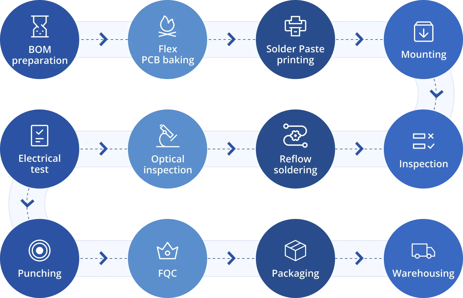
Solder paste printing
Post baking, the board undergoes solder paste printing. In this process solder paste is applied on the PCB surface. The primary goal here is to solder pads onto the circuit board. This is done by screen printing the solder paste through a stencil. A tool called squeegee blade is used to apply the required force on the solder paste to move it across the stencil. Squeegees are generally made of metal or polyurethane.
Reflow soldering
Reflow soldering is a process of pre-heating the components and melting the solder on the PCB to accomplish solder joints between the board and the components. The components are glued to the flex board by the solder paste. This solder paste melts down during the reflow soldering process and cools down to create a good solder joint. This takes place in reflow ovens. These ovens have different heating zones. Each heating zone has its temperature set as per the solder profiles of the assembly process.
Reflow soldering has four stages:
In the preheat stage, heat is accumulated in the board and the components. The temperature should gradually change because quick changes in temperature can damage the components. Generally, the temperature change is no more than 2°C/second. This information can be found in the solder paste datasheet.
During the thermal soak stage, the oxidation of pads and leads of components are reduced by activating the flux.
In the reflow stage, the solder paste is melted and the process reaches its maximum temperature (lesser than the maximum allowed temperature of the components). The processed board is then cooled down and the solder alloy solidifies to create solder joints.
In the further stages, the flex board is optically inspected and electrically tested to ensure it is 100% error free. Post testing, it is punched out of the panel and sent to final quality check (FQC). After FQC the circuit board is sent to packaging and warehousing.

Accommodating Heat Constraints with Flexible Circuits
Another issue that circuit board assemblers need to address is heat sensitivity.
Since flex circuits are much thinner than rigid boards, heat applied for soldering purposes has nowhere to dissipate – it all goes directly through the barrel.
Soldering flexible circuits requires the use of a precise soldering tool in the hands of a highly experienced technician. The margin for error is far lower than with rigid boards.
Continuing advances in the support technology for creating flex circuits ensure that assemblers who invest in state-of-the-art tooling kits and technician training can reduce costs and improve productivity when assembling flex circuits for new products.
Design considerations for flex PCB assembly
Important flex PCB assembly specifications that a designer needs to know.
The most common base material used in flex boards is polyimide films. These materials are flexible and thin. Choose a material with good thermal resistance and electrical conductivity.
The number of layers in a flexible PCB depends on the type of application it is used in. For dynamic applications, opt a single layer board. For static, the number of layers can vary from 4 to 8.
The bend radius of a bendability of it. Generally, the bend radius of these boards vary between 1 mm and 5 mm.
Characteristics of flex board assembly
Application of auxiliary fixtures
Flex boards are prone to wear and tear as they are thin and light weighted. To successfully assemble SMT components, rigid carriers are used. The positioning and consistency of the carrier plays a vital role in the assembly process. Lots of auxiliary fixtures are implemented in flex assembly, including board carrying tray, baking, electrical test, function test, and cutting fixtures.
Low density
The number of components that can be assembled on flex PCBs is relatively low when compared to rigid boards.
High quality requirements
Generally, these boards are used in places where it requires repeated flexing. The components assembled have to meet the demands of their operating conditions. Therefore, flex circuit boards demand higher standards in terms of cleanliness and soldering reliability than rigid PCBs.
By carefully considering the type, size, and mechanical characteristics of components, PCB designers can optimize flexible circuit designs to ensure reliability and performance, particularly in applications where flexibility is critical. As always, collaborating with manufacturers during the design phase can help identify and address potential issues associated with component placement on flexible circuits.
Get started with Printed Circuit Assembly
- Box build assembly
- Flex pcb assembly
- Rigid flex assembly
- SMT Assembly, BGA Assembly, Through hole Assembly, Mixed Assembly