- High frequency low loss PCB material
- Low loss high speed PCB materials
PCB Material
Printed circuit boards (PCB) are embedded into almost all electronic devices. While a PCB is not necessarily needed to make an electronic system, they provide a convenient means of connecting various circuits together through copper routes while also providing a rigid and reliable surface to mount components on. The PCB can have a major impact on many electrical systems and thought should always be given to the choice of PCB material used.
Some key characteristics to consider when choosing a PCB material include the dielectric constant (Dk), dissipation factor (Df), thermal conductivity (TC), and coefficient of thermal expansion (CTE). Other key factors to examine are signal integrity, material cost, and manufacturing cost.
PCB Material Datasheet
Materials covered in this guide can be found below. Click on a material name to download the material’s datasheet.
View More +
PCB Material Properties
The dissipation factor (Df) is the most important in determining the extent of signal loss in a PCB material; a higher value of Df leads to a higher loss. Furthermore, the signal loss also increases with the frequency or speed of operation. Therefore, for controlling the loss at high frequencies or high speeds, choose a PCB material with a low Df value.
Dielectric constant (Dk) of a PCB material changes with frequency. Large variations of Dk with frequency cause larger signal distortion/rise time degradation, which becomes less acceptable for high-frequency or high-speed signals. Therefore, as the signal frequency or speed increases, it is desirable to have lesser and lesser variation in Dk with frequency. The need for less variation of Dk with frequency for low loss PCB materials has been recognized and implemented by all board material manufacturers.
Dielectric constant (Dk)
The Dk of most PCB materials ranges from 2 to 10. The Dk of a PCB material largely determines the trace width of controlled impedance transmission lines on the circuit board; the greater the Dk value, the lesser the trace width will be for the same target controlled impedance value. A higher Dk value also leads to higher dielectric loss. In general, high-speed/low-loss materials have lower Dk values. Thus, Dk becomes an important electrical performance criterion for material selection. For normal speed/normal loss materials, the Dk varies considerably with frequency; for very high speed/very low loss materials, the Dk remains effectively constant with frequency. The Dk of the most commonly used board material- FR4- for example FR370HR- is 3.92 @ 10Ghz.
Dissipation factor (Df)
A material’s dissipation factor is the most important factor in determining the signal attenuation or signal loss, as signals travel along a PCB conductor or trace. The lower a material’s dissipation factor is, the lesser will be the signal loss. Thus, Df is the most important selection criterion from the signal loss perspective. The Df of FR4 material FR370HR is 0.025 @ 10Ghz.
CTI class/voltage
It is a measure of the voltage threshold above which electric breakdown can occur between 2 electrical conductors on the surface of a material. The smaller the CTI class value, the higher the threshold voltage. The CTI of the most commonly used PCB material-FR4- for example FR370HR- is CTI Class 3 with the electric breakdown voltage range being 175V-249V.
Glass transition temperature (Tg)
Tg is the temperature around which a circuit board substrate transitions from a glassy, rigid state to a softened, deformable state. Above Tg, the material has a substantially higher coefficient of thermal expansion than that below Tg. However, the deformation with temperature around Tg is completely elastic; when the temperature drops down from a temperature higher than Tg to below Tg, the material returns to its original state. For all lead-free (ROHS compatible) materials the Tg requirement is >= 170 °C.The Tg of FR4 material FR370HR- is 180 °C.
Decomposition temperature (Td)
Td is the temperature at which a PCB material chemically decomposes and the change is completely irreversible; once the material crosses Td, it cannot return to its original state after cooling down and therefore becomes totally non-functional. The Td of FR4 material FR370HR is 340 °C.
Coefficient of thermal expansion (CTE) X/Y and Z direction
It is the rate of expansion of a board material in the X, Y, and Z directions as the temperature increases. These values refer to the rate of expansion below Tg. The X, Y CTE of FR4 material FR370HR is (13,14) ppm/°C. The Z-axis CTE of FR370HR is 45 ppm/°C.
Laminates in Stock
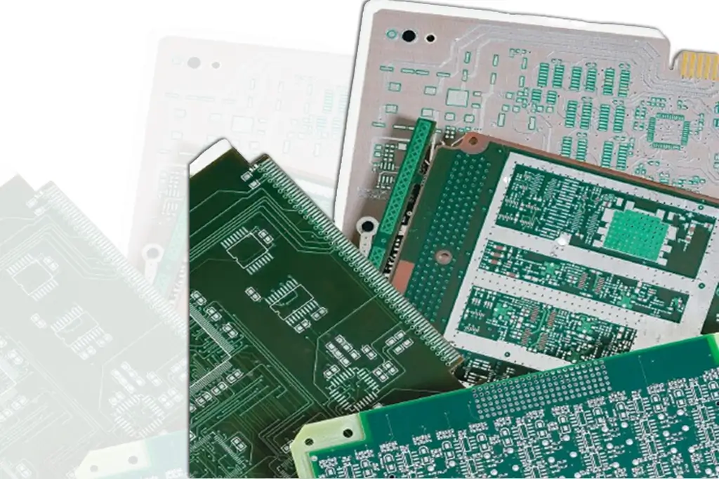
We understand how important it is for you to have those prototypes that you handed over to Benchuang Electronics delivered in a timely manner. To this end, Benchuang Electronics is having all sorts of laminates, especially for those are high Tg, Low Dk/Loss materials available in stock enables us to start to fabricate your urgent requirements without missing a beat. The rare material preparation ahead of time in favor of the lead time of quick-turn projects. That’s customer cares in the highest sense for a quick-turn job.
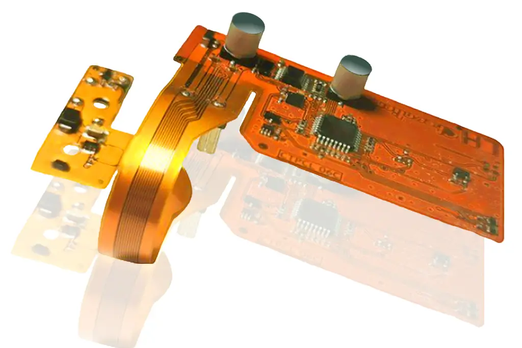
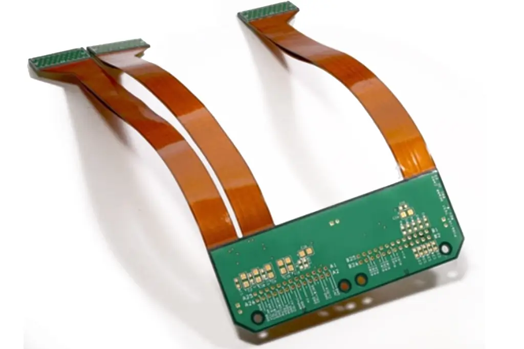
A variety of board materials ranging from FR4 to Microwave/RF PTFE can be retrieved from our warehouse in an instant, get going to meet any urgent PCB’s requirement. No matter what kind of the raw material are designated to apply on your designs; the regular FR4, or High Tg (e.g., Arlon, Nelco, Getek, Isola), High frequency& Low DK/Loss (e.g., Rogers, Taconic, etc.), flex, rigid-flex, or other types of laminate, we have them all for you.
Get Touch For PCB Manufacturing and Assembly
- High frequency low loss PCB material
- Low loss high speed PCB materials