- SMT Assembly, BGA Assembly, Through hole Assembly, Mixed Assembly
- PCB assembly or Box build assembly service delivers a PCBA or a complete electronics assembly in a box
High-Quality Flexible Printed Circuit Board Assembly & Flexible Circuit Assembly
Flexible PCB Assembly Challenges & Proven Solutions
Flexible printed circuit assembly faces unique challenges due to the board’s thin, lightweight nature and flexibility. Heavy components may cause solder joint cracking or misalignment, while air cushions under unflat flex boards can lead to component displacement during SMT pick-and-place. Our proven solutions include customized rigid carriers with calibrated geometry to ensure flat placement, adaptive vision systems for SMT machines to compensate for dimensional variations, and specialized tooling for double-sided flex boards. For heat sensitivity issues, we use 8-zone reflow ovens with precise temperature ramps (≤2°C/second) to prevent component damage, ensuring consistent solder joint quality even for ultra-thin polyimide substrates.
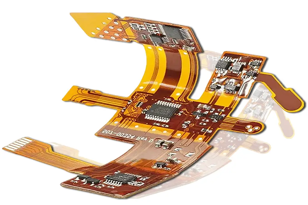
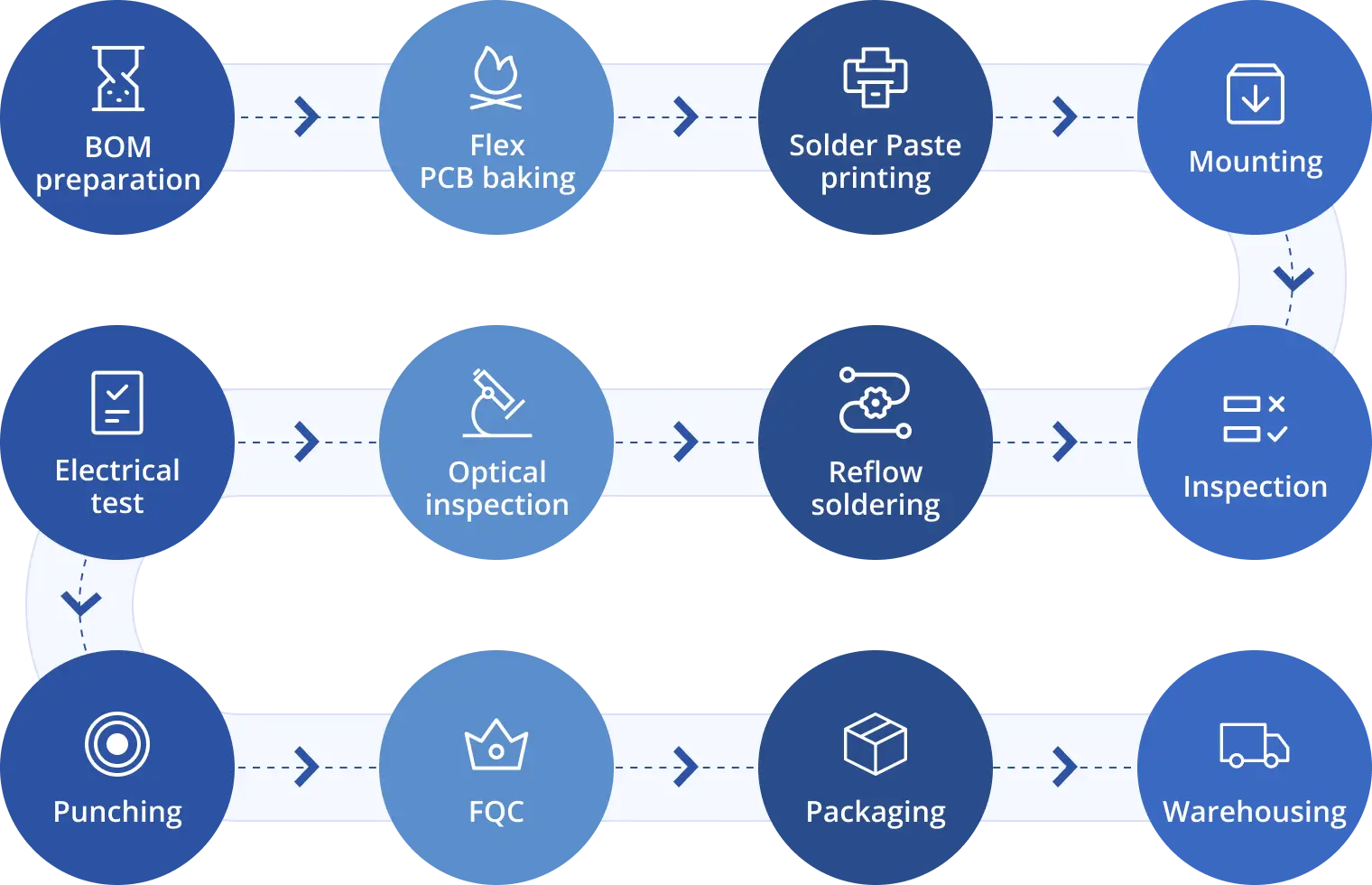
Comprehensive Flexible Printed Circuit Assembly Step-by-Step Process
BOM Preparation for Flexible Printed Circuit Board Assembly
Our BOM preparation for flexible printed circuit board assembly involves rigorous component verification to ensure compatibility with flex substrates. We cross-check part numbers, package sizes (down to 0201 chips), and thermal resistance ratings against the flex board’s specifications. Sourced from authorized distributors (Digi-Key, Mouser), all components meet RoHS standards and come with traceability reports, eliminating the risk of counterfeit parts that could compromise assembly reliability.
PCB Baking Specifications for Flexible PCB Assembly
PCB baking is critical to remove moisture from flex substrates, preventing solder joint voids. We follow industry-leading specifications based on board thickness: up to 1mm (39 mils) requires 2+ hours at 120°C, 1-1.8mm (39-70 mils) needs 4+ hours at 120°C, and 1.8-4mm (70-157 mils) demands 6+ hours at 120°C. Post-baking, boards are cooled in a controlled environment to avoid moisture reabsorption, ensuring optimal solder paste adhesion during the next phase.
Solder Paste Printing for Flexible Circuit Board Assembly
Solder paste printing for flexible circuit board assembly uses laser-cut stencils with 0.1mm minimum aperture size to match fine-pitch pads. We select lead-free solder paste with high-temperature stability (melting point 217°C) compatible with polyimide substrates. A polyurethane squeegee applies uniform pressure (15-20 psi) to ensure consistent paste deposition, and automated inspection checks paste height (±0.02mm tolerance) to prevent bridging or insufficient solder.
Reflow Soldering Process for Bendable Circuit Board Assembly
The reflow soldering process for bendable circuit board assembly follows four stages: preheat (gradual temperature rise to 150°C), thermal soak (150-180°C for flux activation), reflow (peak temperature 220-230°C, <10 seconds dwell), and cooling (rapid temperature reduction to <100°C). Our ovens feature nitrogen atmosphere control to reduce oxidation, and real-time temperature monitoring ensures each board meets the customized solder profile. Post-reflow, X-ray inspection verifies hidden solder joints (e.g., BGA packages) for void-free connections.
Flexible PCB Board Assembly: Critical Design Guidelines
Base Material Selection for Flexible PCB Board Assembly
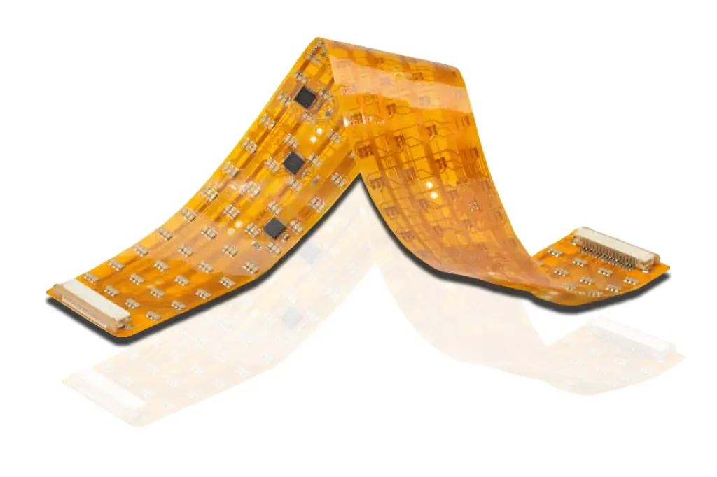
Base material selection for flexible PCB board assembly prioritizes polyimide films (DuPont Kapton) for their excellent thermal resistance (-40°C to 125°C) and mechanical flexibility. For dynamic applications requiring 100,000+ bending cycles, we recommend 25μm-thick polyimide with 1oz copper foil. Static applications (e.g., medical devices) can use multi-layer polyimide (4-8 layers) with FR-4 stiffeners for stability. All materials meet IPC-4201 specifications for electrical conductivity (≥58 MS/m) and dielectric strength (≥20 kV/mm).
Bend Radius Requirements for Bendable Circuit Board Assembly
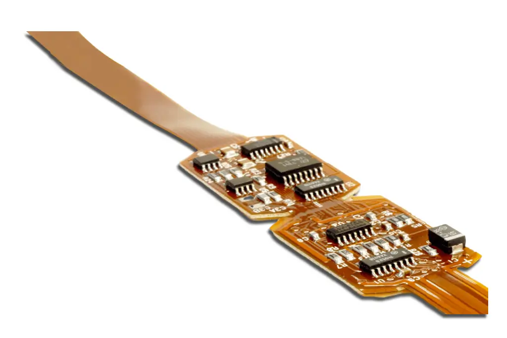
Bend radius requirements for bendable circuit board assembly depend on application type: dynamic bending (repeated flexing) requires a minimum bend radius of 3x the board thickness, while static bending allows 1x-2x the thickness (1mm-5mm typical). We advise avoiding component placement within 2mm of bend lines and using rounded corners to reduce stress concentration. For foldable devices, we optimize trace routing parallel to the bend direction to prevent copper fatigue.
Bendable Circuit Board Assembly: Key Features & Advantages
Our bendable circuit board assembly offers unique features tailored to modern electronics: 100,000+ bending cycle durability, compatibility with ultra-miniature components (0201 chips, 0.4mm pitch BGAs), and IP67-rated conformal coating (Parylene) for harsh environments. Key advantages include space-saving design (fits 3D enclosures), weight reduction (30% lighter than rigid PCBs), and improved vibration resistance. We serve industries including wearables (fitness trackers), medical devices (portable monitors), and automotive (infotainment systems), with a 99.8% on-time delivery rate and 0.3% defect rate—well below industry averages.
Flex Circuit Assembly Challenges
Flex circuits and rigid-flex boards provide manufacturers with significant challenges.
Large or heavy components may pose challenges during the assembly process, requiring careful handling and specialized equipment. The weight of components can affect the quality of solder joints, potentially leading to issues such as solder joint cracking or misalignment.
Whereas the standardized dimensions of rigid PCBs make it easy for assemblers to create highly engineered, conveyor belt-style processes that work for creating a broad range of boards, each individual flex circuit needs to be assessed on an individual scale.
First, the pallet that supports the flex circuit needs to fit its unique, flexible shape.
Ultra-light flex circuits rarely sit flat on a pallet surface, and in the case of double-sided flex circuits, assemblers must design a pallet that accommodates both the top and bottom circuit configuration.
If the flex circuit does not lay flat on the pallet, an air cushion beneath the circuit can generate mechanical resistance during solder paste screening and SMT pick-and-place processes.
Essentially, the air cushion will act like a trampoline and cause components to bounce off the assembly instead of sticking to the circuit membrane.
This requires special tooling and backup fixtures that can be calibrated for unique flexible circuit designs.
Customized pallet geometry ensures that the circuit lays flat even if it has a different thickness at different locations.
SMT pick-and-place machines typically operate at high speed and with an extremely small margin of error. The slightest difference between nominal circuit dimensions and actual flex circuit geometry can generate problems in the assembly process.
Flexible PCB assembly process
Flex board assembly is the process of assembling components. This process is similar to that of rigid boards.
Below image shows the process flow.
Bill of materials
BOM or bill of materials is a list of components required to assemble a printed circuit board.
Flex PCB baking
A flex circuit board stack-up is set and sent to the baking process to reduce the amount of moisture inside the board. The temperature and duration of the baking process depends on the overall thickness of the PCB.
| Overall Thickness of Flex PCB | Duration and Temperature of Baking |
|---|---|
| Up to 1 mm (39 mils) | Minimum 2 hours at 120 °C |
| > 1 mm up to 1.8 mm (70 mils) | Minimum 4 hours at 120 °C |
| > 1.8 mm up to 4 mm (157 mils) | Minimum 6 hours at 120 °C |
Solder paste printing
Post baking, the board undergoes solder paste printing. In this process solder paste is applied on the PCB surface. The primary goal here is to solder pads onto the circuit board. This is done by screen printing the solder paste through a stencil. A tool called squeegee blade is used to apply the required force on the solder paste to move it across the stencil. Squeegees are generally made of metal or polyurethane.
Reflow soldering
Reflow soldering is a process of pre-heating the components and melting the solder on the PCB to accomplish solder joints between the board and the components. The components are glued to the flex board by the solder paste. This solder paste melts down during the reflow soldering process and cools down to create a good solder joint. This takes place in reflow ovens. These ovens have different heating zones. Each heating zone has its temperature set as per the solder profiles of the assembly process.
Reflow soldering has four stages:

In the preheat stage, heat is accumulated in the board and the components. The temperature should gradually change because quick changes in temperature can damage the components. Generally, the temperature change is no more than 2°C/second. This information can be found in the solder paste datasheet.
During the thermal soak stage, the oxidation of pads and leads of components are reduced by activating the flux.
In the reflow stage, the solder paste is melted and the process reaches its maximum temperature (lesser than the maximum allowed temperature of the components). The processed board is then cooled down and the solder alloy solidifies to create solder joints.
In the further stages, the flex board is optically inspected and electrically tested to ensure it is 100% error free. Post testing, it is punched out of the panel and sent to final quality check (FQC). After FQC the circuit board is sent to packaging and warehousing.
Accommodating Heat Constraints with Flexible Circuits
Another issue that circuit board assemblers need to address is heat sensitivity.
Since flex circuits are much thinner than rigid boards, heat applied for soldering purposes has nowhere to dissipate – it all goes directly through the barrel.
Soldering flexible circuits requires the use of a precise soldering tool in the hands of a highly experienced technician. The margin for error is far lower than with rigid boards.
Continuing advances in the support technology for creating flex circuits ensure that assemblers who invest in state-of-the-art tooling kits and technician training can reduce costs and improve productivity when assembling flex circuits for new products.
Design considerations for flex PCB assembly
Important flex PCB assembly specifications that a designer needs to know.
The most common base material used in flex boards is polyimide films. These materials are flexible and thin. Choose a material with good thermal resistance and electrical conductivity.
The number of layers in a flexible PCB depends on the type of application it is used in. For dynamic applications, opt a single layer board. For static, the number of layers can vary from 4 to 8.
The bend radius of a bendability of it. Generally, the bend radius of these boards vary between 1 mm and 5 mm.
Characteristics of flex board assembly
Application of auxiliary fixtures
Flex boards are prone to wear and tear as they are thin and light weighted. To successfully assemble SMT components, rigid carriers are used. The positioning and consistency of the carrier plays a vital role in the assembly process. Lots of auxiliary fixtures are implemented in flex assembly, including board carrying tray, baking, electrical test, function test, and cutting fixtures.
Low density
The number of components that can be assembled on flex PCBs is relatively low when compared to rigid boards.
High quality requirements
Generally, these boards are used in places where it requires repeated flexing. The components assembled have to meet the demands of their operating conditions. Therefore, flex circuit boards demand higher standards in terms of cleanliness and soldering reliability than rigid PCBs.
By carefully considering the type, size, and mechanical characteristics of components, PCB designers can optimize flexible circuit designs to ensure reliability and performance, particularly in applications where flexibility is critical. As always, collaborating with manufacturers during the design phase can help identify and address potential issues associated with component placement on flexible circuits.
Get started with Printed Circuit Assembly
- Box build assembly
- Flex pcb assembly
- Rigid flex assembly
- SMT Assembly, BGA Assembly, Through hole Assembly, Mixed Assembly