
What Is a Flexible PCB? The Definitive Guide to Flexible Printed Circuit Boards
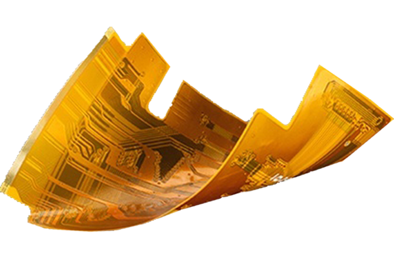
A flexible PCB (flexible printed circuit board) is a versatile electronic interconnection solution built on a bendable dielectric substrate, typically polyimide or polyester. Unlike rigid PCBs, flexible printed circuits can conform to complex shapes, withstand repeated bending, and fit into tight spaces—making them indispensable for modern electronics where miniaturization and durability are paramount. This guide breaks down everything you need to know about flexible PCBs, from their key features and types to real-world applications and essential design considerations.
Flexible PCB Features & Benefits: Why Choose Flexible Printed Circuits
Flexible PCBs offer a unique combination of physical and performance attributes that address critical challenges in electronic design. Their advantages stem from the flexible substrate material and advanced manufacturing techniques, making them a preferred choice across industries.
Core Features
- Bendability & Conformability: Can be folded, twisted, or curved to fit 3D spaces and irregular shapes, enabling design flexibility impossible with rigid PCBs
- Compact Form Factor: Thickness ranges from 0.05mm to 0.80mm, with minimal weight (up to 70% lighter than equivalent rigid PCBs)
- Material Durability: Polyimide substrates resist high temperatures (up to 260°C), chemicals, moisture, and UV radiation
- Conductive Options: Copper conductors (electrodeposited or rolled annealed) with thicknesses from 9µm (1/4 oz) to 70µm (2 oz)
- Layer Configurations: Single-layer, double-layer, or multilayer (up to 12 layers) with plated through-holes (PTH) for interlayer connections
- Precision Engineering: Minimum track and spacing as tight as 0.06mm/0.065mm, supporting high-density interconnect (HDI) designs
- Surface Finishes: Available in ENIG, OSP, immersion silver, immersion tin, and electrolytic gold for corrosion resistance and solderability
Key Benefits
- Space Optimization: Reduces overall device size by up to 40% by conforming to component shapes and eliminating bulky wire harnesses
- Weight Reduction: Critical for aerospace, automotive, and wearable devices, with weight savings of 30-50% compared to rigid PCBs
- Reliability Enhancement: Withstands up to 10,000+ flexing cycles without conductor failure, ideal for dynamic applications
- Vibration & Shock Resistance: Lower stiffness and mass minimize energy transmission, reducing failure risk in high-vibration environments
- Cost Savings: Replaces hand-wired assemblies, cutting wiring costs by up to 70% and reducing assembly time by 20-30%
- Improved Thermal Management: Polyimide substrates offer better heat dissipation than rigid PCB materials, reducing component operating temperatures by 10-15°C
Simplified Assembly: Eliminates the need for connectors and fasteners, reducing part count and human error during production
Flexible PCB vs. Rigid PCB: Core Differences
| Parameter | Flexible PCB | Rigid PCB |
|---|---|---|
| Substrate Material | Polyimide, polyester (PET), PEN | FR4, ceramic, metal core |
| Form Factor | Thin (0.05-0.80mm), bendable | Thick (1.0-4.0mm), rigid |
| Weight | 30-50% lighter | Heavier due to rigid substrate |
| Design Flexibility | Conforms to 3D shapes, dynamic flexing | Limited to flat or fixed configurations |
| Vibration Resistance | High (withstands 10-20G shocks) | Moderate (prone to solder joint failure) |
| Assembly Complexity | Low (integrated interconnects) | High (requires connectors/wire harnesses) |
| Cost | Higher initial tooling cost | Lower upfront cost for simple designs |
| Ideal Applications | Wearables, automotive, medical implants | Desktop computers, industrial controllers |
Common Applications of Flexible PCBs: Where Flexible Printed Circuits Excel
Flexible PCBs are used across industries where space, weight, durability, and design flexibility are critical. Their ability to perform in harsh environments and conform to tight spaces makes them essential for cutting-edge electronics.
Consumer Electronics
- Smartphones & Tablets: Connect displays, cameras, and batteries, enabling slim designs and foldable screens
- Wearable Devices: Smartwatches, fitness trackers, and VR headsets rely on lightweight, skin-conforming flexible PCBs
- Laptops & Ultrabooks: Link keyboards, touchpads, and internal components while reducing overall weight
- Digital Cameras: Connect image sensors, LCDs, and control buttons in compact, ergonomic designs
Automotive Industry
- Advanced Driver-Assistance Systems (ADAS): Connect sensors, cameras, and radar modules in tight engine bay or dashboard spaces
- Infotainment Systems: Link displays, speakers, and controls with vibration-resistant flexible circuits
- Electric Vehicles (EVs): Reduce weight and improve reliability in battery management systems and powertrain components
- Interior Electronics: Connect door locks, window controls, and seat sensors with space-saving flexible interconnects
Medical Devices
- Implantable Devices: Pacemakers, cochlear implants, and neurostimulators use biocompatible flexible PCBs for long-term reliability
- Wearable Medical Equipment: Blood glucose monitors and heart rate sensors benefit from lightweight, flexible designs
- Diagnostic Tools: Endoscopes, ultrasound probes, and portable analyzers use flexible PCBs to fit into compact, ergonomic form factors
- Surgical Instruments: Connect miniaturized motors and sensors in precision surgical tools
Aerospace & Defense
- Aviation Electronics: Reduce weight in avionics systems, including navigation and communication equipment
- Defense Systems: Withstand extreme temperatures and vibrations in missile guidance systems and radar modules
- Satellite Components: Minimize weight and space in satellite payloads and communication systems
- Unmanned Aerial Vehicles (UAVs): Enable lightweight, compact designs for flight control and sensor systems
Industrial & IoT
- Industrial Automation: Connect sensors and actuators in robotics and manufacturing equipment
- IoT Devices: Support compact, low-power designs for smart home sensors and industrial monitors
- Railway Electronics: Withstand vibration and temperature fluctuations in train control systems
- Power Electronics: Improve thermal management and reduce size in inverters and power converters
Types of Flexible PCBs: Classifications & Configurations
Flexible printed circuits are categorized by layer count, structure, and intended use, each designed to meet specific application requirements. Classifications align with IPC-6013 standards, ensuring consistency across manufacturing.
By Layer Count (IPC-6013 Standards)
- Single-Sided Flexible PCB (Type 1): One conductive copper layer with a polyimide substrate and coverlay. Ideal for simple interconnects in low-cost applications. Features include:
- Thickness: 0.05-0.20mm
- Copper weight: 9-35µm (1/4 oz to 1 oz)
- Common uses: Simple sensors, low-power devices
- Double-Sided Flexible PCB (Type 2): Two conductive layers with plated through-holes (PTH) for interconnection. Offers more routing options while maintaining flexibility:
- Thickness: 0.10-0.30mm
- Copper weight: 9-70µm (1/4 oz to 2 oz)
- Common uses: Smartphone cameras, automotive sensors
- Multilayer Flexible PCB (Type 3): Three or more conductive layers with blind, buried, or through vias. Supports complex, high-density designs:
- Thickness: 0.20-0.80mm
- Layer count: Up to 12 layers (without UL certification)
- Common uses: Medical implants, aerospace electronics
By Structure
- Rigid-Flex PCB: Combines flexible and rigid sections, eliminating connectors and reducing assembly complexity. Ideal for devices requiring both flexibility and component mounting rigidity.
- Semi-Flex PCB: Offers limited bendability (1-5mm bend radius) for applications needing occasional shaping without repeated flexing.
- Adhesiveless Flexible PCB: Uses direct copper deposition on polyimide, enabling finer lines and spaces for HDI designs.
- Dynamic Flexible PCB: Designed for repeated bending (10,000+ cycles) with rolled annealed (RA) copper for enhanced durability.
By Application Type
- Static Flexible PCB: Used in fixed bent configurations (e.g., folded inside a device) with no repeated movement.
- Dynamic Flexible PCB: Engineered for continuous bending or flexing (e.g., robotic arms, folding displays) with specialized materials.
- 3D Interconnect Flexible PCB: Designed to conform to complex 3D shapes, replacing traditional wire harnesses.
Considerations for Flexible PCBs: Design, Material & Manufacturing Factors
Successful implementation of flexible printed circuits requires careful consideration of design, material selection, and manufacturing processes to ensure performance and reliability.
Design Considerations
- Bend Radius: Minimum bend radius typically 1-5mm; dynamic applications require larger radii (5x board thickness for static bends, 10x for dynamic)
- Trace Routing: Avoid sharp corners (use 45° angles or curves) to prevent stress concentration; keep traces parallel to bend axes
- Component Placement: Mount heavy components on stiffener areas (FR4 or polyimide) to reduce stress on solder joints
- Via Placement: Avoid placing vias in bend areas; use plated through-holes for interlayer connections in non-flexing regions
- Impedance Control: Maintain consistent trace width and dielectric thickness for high-speed signals (50Ω for single-ended, 100Ω for differential)
Material Selection
- Substrate Materials:
- Polyimide (PI): Most common, offering high temperature resistance (up to 260°C) and flexibility. Ideal for harsh environments and soldering.
- Polyester (PET): Lower cost, suitable for low-temperature applications (up to 120°C) with no soldering.
- PEN: Balances cost and performance, offering better chemical resistance than PET.
- Conductive Materials:
- Electrodeposited (ED) Copper: Cost-effective for static applications.
- Rolled Annealed (RA) Copper: More flexible for dynamic applications, resisting fatigue from repeated bending.
- Adhesives: Acrylic or epoxy-based adhesives for bonding layers; adhesiveless laminates for HDI designs.
- Stiffeners: FR4, polyimide, or aluminum stiffeners for component mounting areas and connector support.
Manufacturing Considerations
- Fabrication Processes:
- Subtractive Method: Etches copper from a solid layer to create traces; cost-effective for high-volume production.
- Additive Method: Deposits copper only where needed; ideal for fine lines and spaces (down to 0.06mm).
- Assembly Requirements:
- Baking: Required to remove moisture (2-6 hours at 120°C, depending on thickness).
- Solder Paste Printing: Uses stencils and squeegees for precise application on flexible substrates.
- Reflow Soldering: Requires controlled temperature profiles to prevent substrate damage (max temperature <260°C).
- Fixturing: Rigid carriers or trays are needed to stabilize flexible PCBs during assembly.
- Quality Control:
- Visual Inspection: Checks for trace damage, solder joint quality, and proper component placement.
- Electrical Testing: Verifies continuity, insulation resistance, and impedance matching.
- Mechanical Testing: Validates flex life and bend durability for dynamic applications.
Cost Considerations
- Initial Tooling Costs: Higher than rigid PCBs due to specialized materials and processes.
- Volume Economics: Costs decrease with production volume; cost-effective for runs of 10,000+ units.
- Total Cost of Ownership: Lower long-term costs due to reduced assembly time, fewer components, and higher reliability.
- Material Costs: Polyimide substrates cost 2-3x more than FR4; unusual thicknesses (9µm or 150µm) increase costs by 2-3x.
FAQ: Common Questions About Flexible PCBs
What is the difference between flexible PCB and rigid-flex PCB?
Flexible PCBs are fully bendable, while rigid-flex PCBs combine flexible sections with rigid areas for component mounting. Rigid-flex eliminates connectors between flexible and rigid parts, reducing assembly complexity and improving reliability.
How long do flexible PCBs last?
Static flexible PCBs (fixed bent configurations) have a service life of 10+ years. Dynamic flexible PCBs (repeated bending) can withstand 10,000-100,000 flex cycles depending on material selection and design.
Can flexible PCBs be repaired?
Repair is challenging due to the protective coverlay and delicate traces. Minor repairs (e.g., solder joint touch-ups) are possible with specialized tools, but major damage typically requires replacement.
What temperature range can flexible PCBs withstand?
Polyimide-based flexible PCBs operate from -55°C to 260°C, making them suitable for harsh environments. PET-based designs have a narrower range (-40°C to 120°C) for low-temperature applications.
When should I choose a flexible PCB over a rigid PCB?
Choose flexible PCBs if your application requires compact design, weight reduction, 3D conformability, vibration resistance, or replacement of wire harnesses. Rigid PCBs are better for low-cost, simple designs with no space constraints.
Conclusion: The Future of Flexible PCBs
Flexible PCBs have revolutionized electronic design by enabling miniaturization, weight reduction, and design flexibility impossible with rigid PCBs. Their unique combination of durability, performance, and conformability makes them essential for the next generation of electronics—from foldable devices to life-saving medical implants.
As technology advances, flexible printed circuits will continue to evolve with new materials (e.g., stretchable substrates) and manufacturing processes (e.g., additive manufacturing) driving further innovation. The growing demand for compact, lightweight, and reliable electronics across industries ensures that flexible PCBs will remain a critical technology for years to come.
By understanding the features, types, applications, and considerations of flexible PCBs, designers and engineers can unlock new possibilities and create products that push the boundaries of what’s possible in electronic design. Whether you’re developing a wearable device, automotive component, or aerospace system, flexible PCBs offer the performance and flexibility needed to succeed in today’s competitive market.


![Understanding PCB Costs & Pricing [Your Complete Guide]](https://hdicircuitboard.com/wp-content/uploads/elementor/thumbs/Understanding-PCB-Costs-Pricing-Your-Complete-Guide-qzzhe6mcaxuolkux3xalfktgavumi9y1aqfbs9bpv4.webp "Understanding PCB Costs & Pricing [Your Complete Guide]")


