







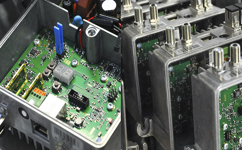
Electromechanical assembly combines printed circuit board assemblies, mechanical hardware, wiring, connectors, motors, sensors, power devices, firmware, and enclosures into a functional system. Reliable production requires more than installing components in a housing: the manufacturer must control mechanical alignment, fastener torque, electrical clearances, grounding, cable routing, thermal interfaces, connector retention, software configuration, and system-level testing. A complete manufacturing package, numerical acceptance limits, qualified tooling, and unit-level traceability reduce rework and prevent failures that cannot be detected during standalone PCB assembly.
A controlled electromechanical assembly program normally includes:
- Design and document review
- Incoming material inspection
- Mechanical subassembly
- PCB assembly installation
- Cable and harness integration
- Grounding and thermal integration
- Firmware loading and configuration
- Electrical and functional testing
- Final inspection and serialization
- Packaging and shipment release
What Is Electromechanical Assembly?
Integrated System Definition
An electromechanical assembly is a product or subassembly that combines electrical operation with a mechanical structure. It may range from a small control module to a complete industrial system.
Common configurations include:
- PCB assembly mounted in a sheet-metal enclosure
- Motor controller with a power supply and cooling fan
- Instrument panel with displays, switches, and wiring
- Sensor module with connectors and mechanical mounting features
- Industrial controller with multiple PCBAs and cable harnesses
- Medical or laboratory device with firmware and calibration
- Rack-mounted electronic box build with removable modules
The operating principle is interaction. A PCB may pass electrical testing, and an enclosure may pass dimensional inspection, but the final system can still fail because of connector misalignment, insufficient grounding, cable abrasion, poor airflow, or incorrect firmware.
The manufacturing value of system-level integration is that these interactions are identified before shipment.
Assembly Scope Levels
| Assembly Level | Typical Content | Required Verification |
|---|---|---|
| Mechanical integration | PCBA, enclosure, standoffs, screws, and labels | Fit, clearance, torque, and appearance |
| Electromechanical assembly | PCBAs, harnesses, fans, switches, power supply, and chassis | Wiring, grounding, thermal contact, and functional test |
| Complete box build | Multiple boards, firmware, calibration, user interfaces, and packaging | System performance, configuration, traceability, and shipment release |
The scope must state whether the delivered product is:
- Mechanically assembled only
- Electrically connected but unpowered
- Powered and functionally tested
- Calibrated to specified limits
- Programmed with production firmware
- Serialized and packaged as a finished product
Ambiguous scope definitions produce inaccurate quotations and incomplete test coverage.
Required Production Data
A release package should contain:
- Bill of materials with approved manufacturer part numbers
- PCB assembly drawings and Gerber or ODB++ data
- Mechanical drawings with tolerances
- Three-dimensional STEP model
- Exploded assembly drawing
- Wire harness drawings and connector pinouts
- Schematic and wiring diagrams
- Fastener and torque specifications
- Firmware files and checksum
- Functional test procedure
- Cosmetic acceptance criteria
- Label and barcode artwork
- Packaging instructions
- Engineering change history
Every drawing, BOM, firmware file, and test program should use the same controlled revision.
Mechanical Components
Enclosures and Chassis
Common enclosure materials include:
- 0.8–2.0 mm sheet steel
- 1.0–3.0 mm aluminum
- Injection-molded ABS or polycarbonate
- Machined aluminum for thermal or precision assemblies
- Stainless steel for corrosion-resistant equipment
Critical dimensions include:
- PCB mounting-hole location: typically ±0.10–0.25 mm
- Connector opening position: typically ±0.15–0.30 mm
- Standoff height: commonly ±0.10 mm
- Cover-to-component clearance: normally 1.0–3.0 mm
- PCB-to-metal clearance: normally at least 2.0–3.0 mm unless an approved insulator is used
A connector panel shifted by 0.5 mm can load the solder joints even when the connector can still be forced through the opening.
Fasteners and Retention
Fasteners should be specified by size, material, finish, washer type, thread-locking method, and torque.
Typical starting ranges are:
| Fastener | Typical Torque Range |
|---|---|
| M2 steel screw | 0.15–0.25 N·m |
| M2.5 steel screw | 0.30–0.50 N·m |
| M3 steel screw | 0.50–0.90 N·m |
| M4 steel screw | 1.20–2.00 N·m |
| Plastic-thread screw | Validated by boss geometry and material |
These are process-development ranges, not universal acceptance limits. Final torque must be validated against thread engagement, material strength, washer design, locking compound, and service load.
Production tools should provide:
- Programmed torque settings
- Tool calibration status
- Error detection for cross-threading
- Barcode-controlled program selection
- Recorded torque for critical joints
Thermal and Moving Parts
Thermal integration may include:
- Heat sinks
- Fans and blowers
- Thermal pads
- Thermal grease
- Heat spreaders
- Insulating thermal films
Typical controls include:
- Thermal pad thickness: 0.5–3.0 mm
- Target pad compression: approximately 10%–30%
- Fan clearance from harnesses: at least 5–10 mm
- Heat-sink screw tightening in a cross pattern
- Temperature verification at maximum specified load
Motors, relays, solenoids, and actuators also require checks for:
- Shaft alignment
- Mechanical travel
- Stall current
- End-stop operation
- Vibration
- Mounting rigidity
Electrical Components
PCB Assemblies and Power Devices
The PCB assembly is normally the functional center of an electronic box build. Acceptance should cover:
- Correct PCBA revision
- Component polarity
- Solder-joint workmanship
- Connector condition
- Conformal coating where specified
- Cleanliness
- Programming status
- Electrical test record
IPC-A-610J defines acceptance criteria for completed electronic assemblies, while IPC J-STD-001J addresses soldering materials and process requirements. Both J revisions were released in 2024.
Power-system components may include:
- AC/DC or DC/DC power supplies
- Circuit breakers
- Fuses
- Contactors
- Relays
- EMI filters
- Terminal blocks
- Battery packs
The factory must verify input range, output voltage, current capacity, polarity, protective earth, and connector keying before power-up.
Sensors and User Interfaces
Typical integrated devices include:
- Temperature sensors
- Pressure sensors
- Encoders
- Limit switches
- Touchscreens
- Keypads
- Indicator lamps
- Emergency-stop switches
Each device requires numerical acceptance limits. Examples include:
- Temperature sensor offset: within ±1.0°C
- Analog input accuracy: within ±1.0% of full scale
- Switch actuation: verified for every position
- Display brightness: tested against an approved visual sample
- Encoder count: matched to the programmed resolution
- Emergency-stop contact resistance: drawing-defined
“Verify operation” is not a repeatable production instruction.
Grounding and Electrical Safety
Grounding serves three purposes:
- Personnel safety
- Electromagnetic compatibility
- Signal stability
A protective-earth joint commonly uses:
- Dedicated stud
- Ring terminal
- Star washer
- Locking hardware
- Unpainted conductive contact area
- Controlled torque
Paint, anodization, or powder coating beneath a grounding point can create high contact resistance. The contact surface should be masked during finishing or prepared through an approved process.
Safety-related tests may include:
- Ground-bond resistance
- Dielectric withstand
- Insulation resistance
- Leakage current
- Polarity verification
Test voltage, current, duration, and acceptance limits must follow the product specification and applicable regulatory standard.
Cable Routing and Connectors
Harness Design Controls
IPC/WHMA-A-620 defines requirements and acceptance practices for cable, wire, and harness assemblies.
Typical harness controls include:
| Harness Feature | Production Control |
|---|---|
| Wire strip-length tolerance | ±0.5 mm |
| Short harness length tolerance | ±5 mm |
| Heat-shrink overlap | 5–15 mm |
| Cable-tie spacing | 50–150 mm |
| Bend radius | 6–10× cable diameter |
| First retention point | 20–50 mm from connector |
Crimped terminals should be controlled by:
- Approved terminal and wire combination
- Calibrated crimp applicator
- Strip-length inspection
- Conductor crimp-height measurement
- Insulation support inspection
- Pull-force testing
- Terminal insertion and lock verification
Visual inspection alone cannot confirm crimp integrity.
Routing and Separation
Cable routing should prevent:
- Contact with sharp metal edges
- Fan-blade interference
- Heat-sink contact
- Pinching beneath covers
- Excessive connector tension
- Abrasion during vibration
- Tight bends at connector exits
- Parallel routing of noisy power and sensitive signals
A practical starting separation between switching-power and low-level signal wiring is 10–25 mm. The actual requirement depends on current, switching frequency, shielding, signal sensitivity, and enclosure geometry.
Where separation is impossible:
- Cross power and signal cables near 90°
- Use twisted pairs for differential signals
- Apply shielding where required
- Define shield termination at one or both ends
- Fix the harness position with clamps
- Avoid uncontrolled service loops
Connector Retention
Connector control includes:
- Correct mating part
- Pin-one orientation
- Keying verification
- Full insertion
- Latch engagement
- Backshell torque
- Strain relief
- Contact retention
For critical connectors, production fixtures can verify insertion depth or latch position. Paint marks can confirm that threaded circular connectors reached the approved torque, but the mark does not replace torque control.
Harness vs Point Wiring
| Factor | Preassembled Harness | Point-to-Point Wiring |
|---|---|---|
| Repeatability | High | Operator-dependent |
| Production Speed | Faster at volume | Slower |
| Engineering Change Flexibility | Lower after release | Higher |
| Tooling Cost | Higher initially | Lower initially |
| Error Prevention | Strong with keyed connectors | Requires inspection |
| Best Application | Medium and high-volume production | Prototype and low-volume production |
Assembly Process
Engineering and Material Review
Before production, the manufacturer should complete:
- BOM and drawing revision comparison
- Three-dimensional interference review
- Cable-length and routing review
- Fastener accessibility review
- Thermal-path evaluation
- Test-point access review
- Assembly sequence planning
- Fixture and tooling definition
Incoming inspection should verify:
- Part number
- Revision
- Quantity
- Dimensions
- Finish
- Connector configuration
- Electrical rating
- Cosmetic condition
Critical components should be traceable by manufacturer lot or date code.
Controlled Build Sequence
A typical process is:
- Install inserts, studs, standoffs, and grounding hardware.
- Mount fans, power supplies, transformers, and heavy parts.
- Install thermal interface materials.
- Mount the primary PCB assembly.
- Install secondary boards and panels.
- Route and connect cable harnesses.
- Secure cables and verify strain relief.
- Load firmware and configuration data.
- Close the enclosure.
- Perform functional and final inspections.
The sequence must preserve access. Installing a PCBA too early may block a grounding nut or cable clamp.
Workmanship and Traceability
Work instructions should include:
- Photographs of cable paths
- Connector orientation
- Torque values
- Tool program
- Adhesive quantity
- Label position
- Firmware revision
- Test limits
- Packaging method
Unit records should link:
- PCBA lot
- Harness lot
- Critical component lots
- Firmware version
- Torque record
- Test result
- Operator
- Date
- Serial number
Testing Requirements
Electrical Testing
Initial power-up should use controlled conditions:
- Polarity verification
- Current-limited power source
- Expected inrush-current allowance
- Voltage-rail measurement
- Abnormal heating check
- Fan operation verification
Example numerical limits may include:
- 5 V rail: 4.85–5.15 V
- 12 V rail: 11.64–12.36 V
- 24 V rail: 23.28–24.72 V
- Standby current: less than 150 mA
- Operating current: 1.20–1.60 A
- Boot time: less than 30 seconds
Limits must come from the approved system specification.
Functional and Integration Tests
Functional testing may verify:
- Display
- Buttons
- LEDs
- Sensors
- Motor direction
- Relay outputs
- Fan speed
- Ethernet
- USB
- CAN
- RS-485
- Wireless connection
- Firmware checksum
- Alarm states
| Test Method | Primary Purpose | Main Limitation |
|---|---|---|
| In-circuit Test | Detects component, short, and open defects | Cannot verify complete system operation |
| Flying Probe Test | Flexible testing for prototypes | Longer test time |
| Functional Test | Confirms product operation under conditions | Fault isolation can be slower |
| System Integration Test | Verifies interfaces, firmware, and configuration | Requires dedicated fixtures and software |
Reliability Testing
Depending on product requirements, validation can include:
- Burn-in for 2–24 hours
- Thermal cycling
- Vibration
- Mechanical shock
- Drop testing
- Humidity exposure
- Connector mating-cycle testing
- Cable flex testing
Production burn-in should be based on an identified reliability objective. Extending burn-in without failure-mode analysis adds cost but does not guarantee better reliability.
Quality Control
Inspection Gates
A controlled process normally uses:
- Incoming inspection
- Mechanical subassembly inspection
- PCB assembly acceptance
- Harness inspection
- In-process electrical test
- Final functional test
- Cosmetic inspection
- Packaging audit
Typical controls include:
| Inspection Item | Acceptance Requirement |
|---|---|
| Fastener Torque | Within drawing limit and recorded for critical joints |
| Connector Engagement | Fully seated, keyed, and locked |
| Harness Routing | No pinch, abrasion, tension, or interference |
| Thermal Interface | Correct material, position, and compression |
| Firmware | Approved version or checksum verified |
| Functional Test | 100% pass within defined limits |
| Labels | Correct part number, serial number, and revision |
| Traceability | Complete unit history available |
ISO 9001:2015 provides the current published framework for a quality management system, while ISO has also published a final draft for a planned replacement edition expected in 2026.
Nonconforming Product
Failed units should enter a controlled nonconforming area. Records should include:
- Failure code
- Actual measurement
- Suspected cause
- Repair authorization
- Corrective action
- Retest result
- Final disposition
Repeated failures should trigger root-cause analysis rather than repeated repair.
Factory Production Case
Industrial Drive Controller
A factory built a 150-unit pilot run of an industrial electromechanical assembly containing:
- One 10-layer main PCB assembly
- One 4-layer interface PCBA
- 24 VDC input
- 400 W power supply
- Two 80 mm cooling fans
- Twelve cable harnesses
- Four external circular connectors
- Ethernet and RS-485 interfaces
- 1.5 mm aluminum enclosure
- 0.5 mm pitch BGA
- 50-ohm controlled-impedance PCB routing
Initial Production Problems
The first 24 units produced:
- Five intermittent RS-485 failures
- Four pinched fan cables
- Three covers that could not close without force
- Two stripped M3 inserts
- Average assembly time of 52 minutes
- Functional test time of 17 minutes
- First-pass yield of 75.0%
The factory identified:
- RS-485 wiring ran parallel to a switching-power cable for 210 mm.
- Harness length tolerance was ±15 mm.
- Cable clamps had no dimensional datum.
- Cover clearance above the harness was only 1.5 mm.
- The M3 screwdriver program was set to 1.1 N·m instead of 0.7 N·m.
Corrective Actions
The revised design and process used:
- Minimum 20 mm separation between power and RS-485 wiring
- Approximately 90° crossings where separation was impossible
- Harness-length tolerance reduced to ±5 mm
- Two fixed P-clamp positions added to the drawing
- Cover clearance increased to 5.0 mm
- Barcode-locked screwdriver programs
- Start-of-shift torque verification
- Automated firmware and interface testing
- Harness photographs added to work instructions
Measured Improvement
| Measurement | Initial Build | Revised Build |
|---|---|---|
| First-pass Yield | 75.0% | 98.4% |
| RS-485 Failures | 5 of 24 | 0 of 63 |
| Pinched Cables | 4 of 24 | 0 of 63 |
| Damaged Inserts | 2 of 24 | 0 of 63 |
| Assembly Time | 52 minutes | 37 minutes |
| Functional Test Time | 17 minutes | 9 minutes |
| Cover Rework | 3 of 24 | 1 of 63 |
The revised process reduced assembly labor by 28.8%, reduced test time by 47.1%, and improved first-pass yield by 23.4 percentage points.
Common Design Errors
Incomplete Mechanical Definition
Frequent omissions include:
- Missing connector positions
- No mounting-hole tolerance
- No component-to-cover clearance
- No assembly sequence
- No fastener torque
- No thermal-pad thickness
These omissions force operators to interpret engineering intent during production.
Undefined Harness Routing
A schematic defines electrical connectivity but does not define the physical wire path.
Production drawings should identify:
- Harness length
- Routing path
- Clamp position
- Bend radius
- Connector orientation
- Shield termination
- Service-loop length
- Power and signal separation
Missing Test Limits
Instructions such as “test communication” or “verify motor works” are incomplete.
Every test requires:
- Input condition
- Measurement point
- Lower limit
- Upper limit
- Test duration
- Failure code
- Data-recording method
No Assembly Tolerance Study
Tolerance accumulation can cause:
- Connector-panel stress
- Incomplete thermal contact
- PCB bow
- Cover interference
- Cable tension
- Misaligned shafts
Three-dimensional fit review should include worst-case enclosure, standoff, PCB, connector, and cable dimensions.
Supplier Selection
Technical Capability
A qualified supplier should demonstrate:
- PCB assembly capability
- Cable and harness production control
- Mechanical assembly experience
- Torque-controlled tooling
- Firmware programming
- Functional test development
- Traceability
- Engineering change control
- Failure analysis
The supplier should be able to explain how it controls each critical process rather than only listing equipment.
Quality and Process Control
Supplier evaluation should review:
- ISO 9001 certification status
- IPC-trained personnel
- Calibration system
- Incoming inspection
- Nonconforming-material control
- Corrective-action process
- First-article inspection
- Process capability
- Test-data retention
- Revision control
IPC standards are intended to communicate common quality and reliability expectations across electronics manufacturing.
Prototype vs Production Supplier
| Selection Factor | Prototype-Focused Supplier | Production-Focused Supplier |
|---|---|---|
| Engineering Change Speed | High | Controlled |
| Fixture Investment | Limited | Supports automation |
| Unit Labor Cost | Higher | Lower at volume |
| Documentation | Flexible | Formal and revision controlled |
| Material Strategy | Spot purchasing | Forecast and scheduled supply |
| Best Use | Design validation | Pilot and production builds |
FAQ
What is electromechanical assembly?
Question: What does electromechanical assembly include?
Answer: It includes the integration of PCB assemblies, enclosures, fasteners, cables, connectors, power supplies, switches, sensors, motors, thermal parts, firmware, labels, and packaging. The final scope may range from a mechanical subassembly to a fully tested electronic box build.
What tests are required?
Question: How should an electromechanical assembly be tested?
Answer: Testing normally includes visual inspection, torque verification, cable continuity, controlled power-up, voltage and current measurements, interface testing, firmware verification, grounding checks, and full functional testing. Every critical measurement should have numerical limits and traceability to the unit serial number.
What manufacturing files are needed?
Question: What files should an OEM provide to an electromechanical assembly supplier?
Answer: The production package should include the BOM, PCB files, mechanical drawings, three-dimensional models, wiring diagrams, harness drawings, connector pinouts, torque values, firmware, test procedures, label files, packaging requirements, and revision history.
How should a supplier be evaluated?
Question: How do engineers select a reliable electromechanical assembly supplier?
Answer: Evaluate PCB assembly, harness, mechanical integration, programming, testing, traceability, quality-system, and failure-analysis capabilities. Review actual work instructions, calibration records, first-article reports, corrective-action examples, and test-data controls rather than relying only on a general capability list.

![Understanding PCB Costs & Pricing [Your Complete Guide]](https://hdicircuitboard.com/wp-content/uploads/elementor/thumbs/Understanding-PCB-Costs-Pricing-Your-Complete-Guide-qzzhe6mcaxuolkux3xalfktgavumi9y1aqfbs9bpv4.webp "Understanding PCB Costs & Pricing [Your Complete Guide]")