
Built as a hybrid electronic circuit structure, rigid-flex PCB combines rigid substrate sections for component mounting and durable flexible film segments for dynamic movement and three-dimensional installation. This integrated laminated design delivers uninterrupted electrical performance while adapting to complex mechanical bending, folding and spatial assembly demands. Manufactured in full compliance with IPC-2221 and IPC-6012 industry specifications, this composite circuit solution solves structural limitations of traditional single-type boards, improving long-term stability and miniaturization for industrial, automotive and portable electronic systems.
Learn more about: What is Rigid-Flex PCB? A Complete Guide
Rigid Flex PCBs Work
Integrated Circuit Transmission Logic
A rigid-flex circuit operates on unified electrical pathways that span rigid and flexible regions without separate connectors or external wiring. Internal layered interconnection structures link multi-layer circuits stably, maintaining consistent signal quality even during repeated physical deformation. Continuous copper routing eliminates transitional docking points, lowering contact resistance, electromagnetic crosstalk and intermittent circuit faults commonly seen in split board assemblies.
Dual-Material Mechanical Matching
Hard rigid substrates deliver flat, rigid support for surface-mounted components and high-power devices that require fixed positioning. Thin flexible dielectric materials provide structural softness to withstand frequent bending, twisting and folding motions. High-temperature resistant bonding materials balance different thermal expansion rates between rigid and flexible substrates, preventing layer separation and structural deformation under long-term temperature cycling and mechanical stress.
Key Components and Functionality
Core Substrate and Dielectric Materials
High-density rigid-flex circuit construction relies on high-Tg FR-4 rigid boards, polyimide flexible films, modified bonding adhesives and insulating coverlay materials. Rigid substrate grades are selected to sustain peak reflow temperatures up to 260 °C, while polyimide film maintains stable physical properties across -40 °C to 125 °C operating ranges. Intermediate adhesive layers are engineered to reduce thermal mismatch and strengthen overall structural bonding strength throughout mass production.
Functional Circuit Structural Parts
Conductive copper layers, precision etched signal traces, interconnection vias and surface protective coatings form the complete functional framework of each rigid-flex unit. Fine-line etching processes support compact circuit routing, while microvia structures enable high-density layer connection in limited board space. Industrial-standard surface finishes enhance oxidation resistance and soldering reliability, extending service life in high-humidity and vibration-intensive working environments.
Layered Construction
| Structural Layer | Main Raw Material | Actual Thickness Range | Conductive Copper Thickness |
|---|---|---|---|
| Rigid Outer Base | High-Tg FR-4 | 1.0–1.6mm | 35μm |
| Lamination Transition Layer | Epoxy Prepreg Film | 0.15–0.2mm | 18μm |
| Flexible Circuit Core | Polyimide Film | 25–50μm | 12–18μm |
| External Protective Coverlay | PI Insulation Film | 20–30μm | No Conductive Copper |
Symmetrical Stack-Up Design Principles
Commercial rigid-flex circuits adopt symmetrical layer stacking to avoid board warpage, internal stress distortion and lamination defects. Standard 6-layer configurations use rigid panels as outer structural layers, with paired flexible core layers arranged in the middle for balanced stress distribution. Each adhesive transition layer is controlled at fixed thickness to guarantee uniform pressure distribution during high-temperature lamination and stable overall structural flatness.
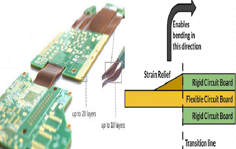
Isolation and Boundary Transition Design
Independent dielectric isolation separates adjacent signal layers to prevent short-circuit risks in high-density wiring areas. Polyimide dielectric materials maintain stable dielectric constant and low loss characteristics required for high-speed signal transmission. Gradual thinning transition zones are added at rigid-flex boundaries to buffer mechanical tension, preventing trace fracture and coverlay damage caused by frequent bending actions.
Learn more about: What is a Rigid-Flex PCB? Design & Manufacturing Best Practices
Component Mounting
Zoned Component Placement Rules
All electronic components and soldered assemblies are restricted exclusively to rigid board sections. No chips, connectors or heavy structural parts are placed inside flexible bending zones. A buffered isolation strip is reserved at every rigid-flex boundary to isolate assembly stress and bending tension, protecting soldered pads and component joints from mechanical fatigue and peeling failure.
Industrial Assembly Process Control
Lead-free reflow soldering parameters are precisely calibrated to protect composite board structures during mass assembly. Flexible sections are covered with high-temperature shielding materials to avoid film aging and adhesive layer degradation under soldering heat. Automated optical inspection is implemented after assembly to detect solder bridging, empty welding and surface damage, ensuring consistent assembly quality for bulk production batches.
Plated Through Holes
Industrial Drilling and Plating Specifications
Plated through hole structures establish vertical electrical connection between stacked internal layers. Standard mechanical drilling handles hole sizes above 0.3mm, while laser micro-drilling fabricates tiny vias for high-density HDI layouts. Electroless copper deposition and electroplating processes form uniform hole-wall copper layers, meeting IPC-2221 thickness requirements and ensuring stable conduction under long-term temperature changes.
Scientific Hole Layout Restrictions
Through-hole structures and dense via groups are strictly kept away from flexible bending sections and transition boundaries. Reasonable hole spacing and edge distance design reduce local structural weakness, maintaining overall bending toughness and preventing layer delamination around hole positions. High-density via clustering is avoided to preserve structural integrity of composite lamination layers.
Flexible Interconnection
Bending Mechanism for Dynamic Application
Flexible interconnection depends on high-toughness polyimide substrates and ductile rolled copper foil to achieve repeated folding and angle adjustment. Internal signal traces adopt curved routing at bending positions to disperse tension and avoid stress concentration. This structural design allows multi-angle deformation, enabling circuit integration inside irregular equipment shells and compact mechanical modules with movable parts.
Long-Term Bending Durability Design
Engineers set differentiated bending radius standards based on static installation or cyclic dynamic use scenarios. Flexible area copper coverage is optimized with grid patterns to reduce overall hardness and enhance torsion resistance. Material selection prioritizes high-ductility copper foil and elastic adhesive systems to extend cycle life in continuous motion applications.
Manufacturing Process
Pre-Production Material and Circuit Fabrication
Full rigid-flex production begins with precision material cutting, inner-layer circuit patterning and copper etching. Flexible core units are covered with customized coverlay films for insulation and surface protection before layered assembly. Professional DFM evaluation is completed in early stages to correct unreasonable boundary design, dense routing and improper hole placement that may affect production yield.
Integrated Lamination and Finishing Steps
Prepared rigid and flexible core layers are positioned and stacked through high-precision tooling fixtures, then pressed under constant temperature and pressure to form an integrated composite board. Subsequent processing includes hole drilling, copper plating, solder mask coating and surface finishing. Finished products undergo full continuity testing and selective bending sampling inspection to screen lamination defects and hidden circuit fractures.
Learn more about: Rigid-Flex PCB Manufacturing Process Step by Step
Primary Benefits
| Performance Item | Rigid-Flex PCB | Ordinary Flex PCB with Stiffener |
|---|---|---|
| Bend Cycle Life | 10,000–100,000 cycles | 1,000–5,000 cycles |
| Long-Term Connection Stability | Low structural fatigue | High adhesive aging risk |
| High-Speed Signal Stability | Controlled impedance tolerance | Unstable impedance fluctuation |
| On-Site Assembly Difficulty | Single-board installation | Multi-part manual assembly |
Miniaturization and Lightweight Optimization
Integrated rigid-flex architecture removes multi-board combination structures and internal connecting wire harnesses, effectively reducing overall device assembly volume and weight. Compact composite layout helps designers develop ultra-thin portable devices, wearable hardware and narrow-space industrial control modules. Integrated circuit layout saves internal structural components and simplifies overall mechanical assembly procedures.
Enhanced Structural Reliability
Monolithic lamination greatly reduces independent connection points and mechanical assembly gaps that easily trigger circuit failure. Optimized boundary transition and stress dispersion design improve vibration resistance and shock tolerance in harsh working environments. Stabilized impedance design and continuous grounding layout suppress high-frequency interference, securing reliable signal transmission for high-speed electronic systems.
Expanded Engineering Design Flexibility
Breaking past limitations of flat rigid circuit boards, flexible segments support curved installation, folding layout and special-shaped structural matching. Customizable layer counts, material combinations and partition proportions adapt to diversified demands across medical, automotive, smart home and industrial automation fields. Modular design logic shortens product iteration cycles and structural docking development time.
Miniaturization
Compact Structural Layout Advantage
Composite rigid-flex design realizes three-dimensional space utilization through foldable and bendable circuit segments. Traditional separate board solutions require reserved space for connectors and wiring, while integrated composite circuits maximize internal space utilization. Thinned stacked structures support ultra-thin product styling and meet lightweight development trends for consumer-grade portable electronics.
High-Density Circuit Integration
Fine-line fabrication and microvia interconnection technology improve wiring density within limited board dimensions. Multi-layer internal stacking expands circuit integration without expanding horizontal board size. Rational functional zoning separates high-power modules, high-speed signal circuits and bending areas, balancing integration density and long-term operational stability.
Reliability
Mechanical Fatigue Resistance
Integrated lamination bonding improves interlayer bonding strength and prevents peeling under vibration and repeated deformation. Specially selected rolled copper materials resist metal fatigue and cracking during long-term cyclic bending. Overall structural optimization weakens local stress points, adapting to continuous mechanical movement in automated equipment and vehicle-mounted electronic units.
Wide Environmental Adaptability
Compliant with IPC-6012 high-reliability grade standards, rigid-flex circuits maintain stable performance under extreme temperature fluctuation and high-humidity conditions. Protective coverlay and industrial surface finishing prevent moisture penetration, dust erosion and chemical corrosion. Reinforced structural design ensures stable operation in outdoor, vehicle and factory industrial environments.
Improved Design Flexibility
Multi-Dimensional Assembly Adaptation
Flexible sections support free angle bending and spatial folding to fit irregular equipment internal structures. Design teams can adjust rigid and flexible area proportions according to product shell contours and movement trajectories. This flexible layout mode solves installation difficulties of special-shaped equipment that cannot be met by traditional flat rigid circuits.
Customized Solution Compatibility
Material grades, layer quantities, bending specifications and surface treatment processes can be adjusted according to different application scenarios. High-temperature resistant versions are customized for automotive power systems, while biocompatible materials are applied for medical portable detection equipment. Targeted design adjustment balances performance, production cost and mass production feasibility.
Better Performance
Optimized High-Speed Signal Integrity
Shorter unified signal paths reduce transmission loss and delay caused by multi-segment connection docking. Accurate dielectric material matching and controlled impedance design stabilize high-frequency signal output and reduce crosstalk interference. Low-loss flexible dielectric materials further improve transmission efficiency for high-speed communication and precision control modules.
Balanced Thermal Dissipation Performance
Rigid zone thickened copper layers accelerate heat diffusion for heat-generating components, while hollow flexible structures enhance natural air circulation. High-temperature resistant substrate materials avoid thermal aging under continuous high-load operation. Reasonable layer stacking design distributes heat evenly and reduces local overheating risks in high-density integrated circuits.
Key Design Considerations
Bend Radius
Scientific radius limitation is the core premise to avoid flexible segment damage. Static structural bending allows smaller dimensional settings, while dynamic cyclic bending requires enlarged reserved radius to release stretching stress. Excessively compressed bending range will cause irreversible copper fatigue and protective film cracking, shortening product service life in actual application.
Stress Management
Stress buffer design must be added at all rigid-flex junction positions to relieve concentrated tension during folding. Large-area solid copper coverage is prohibited in flexible zones to reduce overall structural hardness. Material thermal expansion coefficients are matched in the early design stage to reduce internal thermal stress generated by temperature rise and fall changes.
Trace Routing
Wiring direction inside bending zones follows mechanical movement direction to reduce tensile deformation of signal lines. Sharp right-angle routing is completely avoided in flexible sections and transition zones. High-speed differential groups maintain equal spacing and equal length design to guarantee signal synchronization and transmission accuracy.
Benchuang Electronics
Benchuang Electronics focuses on independent research, customized production and technical support for high-reliability rigid-flex circuits and composite electronic board solutions. The factory operates standardized production workshops with complete sets of precision manufacturing equipment, covering lamination pressing, laser microvia processing, high-precision circuit etching and full-range electrical performance testing. All production procedures follow IPC and international quality management systems, delivering compliant circuit products for industrial control, medical devices, vehicle electronics and consumer smart hardware industries.
With rich manufacturing experience in multi-layer rigid-flex structures, the technical team provides professional DFM optimization, early design review and structural risk assessment for each project. The brand focuses on improving transition zone processing, bending durability enhancement and composite material matching technology, effectively reducing common mass production defects such as layer separation and trace fracture. Short-cycle prototype trial production and stable mass delivery systems meet diverse demands from small-batch research samples to large-scale continuous orders.
Strict quality control runs through every production process, including raw material incoming inspection, mid-process parameter monitoring and finished product sampling verification. Bending cycle testing, impedance detection and high-temperature aging screening are adopted to ensure long-term stability of finished products. As a professional composite circuit supplier, Benchuang Electronics continuously optimizes manufacturing techniques to balance structural performance, production cost and delivery efficiency for global engineering clients.
Learn more about: What is a Flexible PCB? A Complete Guide for Beginners
Core Technical Points
- Minimum line width and spacing: 25μm / 25μm for high-density routing, 50μm / 50μm for standard industrial production
- Microvia and mechanical hole range: 0.1mm laser microvia, 0.3mm–0.8mm standard plated through hole
- Flexible core thickness: 25μm to 50μm polyimide film with 12μm–18μm rolled copper foil
- Rigid board specification: 1.0mm–1.6mm high-Tg FR-4 for enhanced thermal stability
- Bending design standard: 3 times material thickness for static bending, 5 times thickness for dynamic cyclic bending
- Controlled impedance accuracy: ±5% tolerance for mainstream high-speed circuit design
- Continuous working temperature range: -40°C to 125°C for long-term industrial application
- Standard lamination process: 185°C–195°C pressing temperature with stable bonding pressure parameters
Case Study
An 8-layer rigid-flex circuit was customized for vehicle-mounted intelligent sensing modules, requiring long-term dynamic bending and vehicle-grade environmental resistance. In initial trial production, engineers found periodic trace breakage at rigid-flex transition areas after thousands of bending tests, accompanied by minor interlayer separation after multiple reflow cycles.
After on-site process analysis, the technical team corrected unreasonable right-angle routing at boundary zones and upgraded low-CTE bonding film materials to reduce thermal expansion mismatch. Transition buffer width was expanded and arc routing was adopted to disperse mechanical stress. After design revision and process adjustment, revised samples passed full bending life testing and high-temperature aging verification. Final production yield increased significantly, and the finished product achieved stable mass delivery fully meeting automotive reliability standards.
Common Design Errors
- Unqualified bending radius setting that does not match dynamic or static usage conditions, leading to early flexible segment damage.
- Random placement of vias, pads and device components inside flexible zones, causing concentrated stress and structural fracture.
- Unoptimized right-angle routing at rigid-flex boundaries, accelerating copper layer fatigue under repeated folding movement.
- Unmatched thermal expansion parameters between stacked materials, triggering interlayer separation under alternating temperature environments.
- Excess thick copper layout in flexible areas that reduces bending toughness and increases circuit fracture risk.
FAQ
Q: How do rigid-flex PCBs maintain stable signal transmission across dual material zones?
A: Continuous copper traces cross rigid and flexible sections as a whole, with internal plated through holes and buried vias completing layer interconnection. Integrated lamination removes transitional connector gaps, maintaining stable impedance and complete signal pathways during mechanical deformation.
Q: What core design rules control flexible segment service life?
A: Reasonable bending radius limits, stress buffer transition zones, optimized trace routing directions and low-stress copper layout are key design rules. Cooperated with high-ductility flexible copper and matched adhesive materials, these measures effectively extend cyclic bending life.
Q: What practical advantages does rigid-flex PCB have compared with flexible boards with stiffeners?
A: Integrated one-piece lamination delivers stronger structural integrity, longer bending cycle life, more stable impedance control and lower later maintenance failure rates. Separate stiffener bonding belongs to secondary assembly, with obvious aging and peeling risks in long-term use.
Q: What quality measures does Benchuang Electronics use to guarantee rigid-flex board reliability?
A: All products adopt IPC-compliant production specifications, full electrical performance testing and selective mechanical bending sampling inspection. Material matching verification and lamination parameter locking reduce composite structure defects, while early DFM review eliminates design risks in advance.
If you need professional rigid flex pcb design support or quotation, our team provides free DFM check and fast turnaround.


![Understanding PCB Costs & Pricing [Your Complete Guide]](https://hdicircuitboard.com/wp-content/uploads/elementor/thumbs/Understanding-PCB-Costs-Pricing-Your-Complete-Guide-qzzhe6mcaxuolkux3xalfktgavumi9y1aqfbs9bpv4.webp "Understanding PCB Costs & Pricing [Your Complete Guide]")


