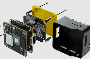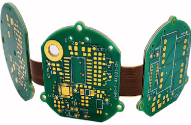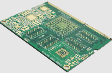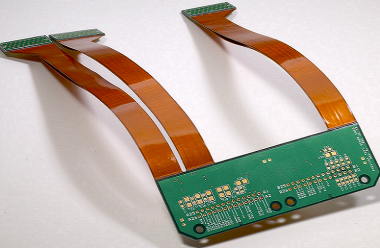




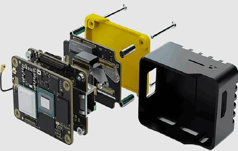
Box build assembly is the controlled integration of printed circuit board assemblies, cables, wire harnesses, power supplies, displays, fans, mechanical parts, firmware, and enclosures into a complete electronic system. A successful box build assembly process does more than place a PCB inside a housing. It verifies mechanical fit, electrical safety, cable routing, grounding, thermal performance, software loading, functional behavior, labeling, traceability, and final product configuration before shipment.
From a factory engineering perspective, the most reliable electronic box build projects begin with a complete manufacturing package. The package should define the bill of materials, assembly drawings, 3D mechanical files, cable drawings, torque values, firmware revision, functional test limits, cosmetic requirements, packaging method, and acceptance class. When these details are controlled before production, box build manufacturing can reduce rework, shorten lead time, and prevent failures that cannot be detected during standalone PCB assembly.
A complete production flow normally includes:
- Incoming material inspection
- PCB assembly verification
- Mechanical subassembly
- Cable and wire harness preparation
- Power, signal, and grounding integration
- Firmware programming
- Functional and safety testing
- Final inspection
- Serialization and labeling
- Packaging and shipment release
What Is Box Build Assembly?
System-Level Integration
Box build assembly combines electronic and mechanical parts into a finished or semi-finished product. Depending on product complexity, the completed unit may be:
- A simple PCB assembly mounted inside a metal enclosure
- A control panel with switches, displays, and wiring
- A power conversion unit with fans and thermal interfaces
- A medical instrument with firmware and calibrated sensors
- An industrial controller with multiple PCBAs and cable harnesses
- A rack-mounted communication system with backplanes and modules
The core principle is system integration. Individual components may pass separate inspections, yet the complete unit can still fail because of grounding, connector orientation, cable strain, airflow restriction, mechanical interference, or software configuration.
The value of box build services is that these interactions are verified before the product reaches the customer.
Box Build Scope Levels
Box build projects vary significantly in complexity.
| Scope Level | Typical Content | Factory Responsibility |
|---|---|---|
| Basic enclosure assembly | One PCBA, enclosure, screws, and labels | Mechanical mounting and visual inspection |
| Electromechanical assembly | PCBAs, cables, switches, fans, power supply, and chassis | Wiring, torque control, grounding, and functional testing |
| Complete system integration | Multiple boards, firmware, calibration, displays, networking, and packaging | Full configuration, validation, traceability, and shipment release |
A customer selecting a box build assembly supplier should define whether the product must leave the factory as:
- An assembled mechanical unit
- A powered and tested electronic system
- A calibrated product
- A customer-ready finished device
- A serialized and packaged retail or industrial product
This distinction directly affects tooling, labor, testing, compliance, and lead time.
Required Manufacturing Files
A complete data package normally includes:
- BOM with approved manufacturer part numbers
- Gerber or ODB++ files for PCB assembly
- Pick-and-place data
- Mechanical drawings
- 3D STEP model
- Exploded assembly drawing
- Cable and wire harness drawings
- Schematic diagrams
- Firmware files and revision instructions
- Test procedures and acceptance limits
- Label artwork
- Packaging specifications
- Engineering change history
A drawing that only shows the external enclosure is not sufficient. The factory also needs internal routing, connector orientation, torque requirements, grounding locations, and sequence-dependent assembly steps.
Box Build Assembly Process
Incoming Material Control
The process begins with incoming inspection. Each critical part should be matched against the BOM, drawing revision, and approved supplier list.
Typical incoming controls include:
- Enclosure dimensions: ±0.10 to ±0.30 mm for machined features
- Sheet-metal thickness: commonly 0.8–2.0 mm
- Surface coating thickness: approximately 20–80 µm, depending on finish
- Connector keying and pin count verification
- Cable length tolerance: commonly ±5 mm for short harnesses
- Fan voltage and airflow confirmation
- Power supply input and output rating verification
- Label text, barcode, and revision inspection
Critical mechanical parts should be checked with calipers, gauges, or a coordinate measuring machine when hole position affects PCB or connector alignment.
A recurring factory issue is receiving enclosure parts with correct overall dimensions but incorrect hole offsets. A 0.5 mm connector-panel mismatch may prevent proper assembly even when the PCB is manufactured correctly.
Mechanical Subassembly
Mechanical assembly should follow a defined sequence because later components may block access to screws, washers, or connectors.
A typical sequence is:
- Install threaded inserts, standoffs, and grounding hardware.
- Mount fans, power supplies, and large mechanical components.
- Apply thermal pads or interface materials.
- Install the main PCB assembly.
- Add secondary boards and interface panels.
- Connect cable harnesses.
- Secure wires and apply strain relief.
- Complete final enclosure closure.
Typical torque ranges include:
| Fastener | Typical Torque Range |
|---|---|
| M2 steel screw | 0.15–0.25 N·m |
| M2.5 steel screw | 0.30–0.50 N·m |
| M3 steel screw | 0.50–0.90 N·m |
| M4 steel screw | 1.2–2.0 N·m |
| Plastic-thread screw | Defined by boss material and test data |
Torque values must be validated for the actual fastener, washer, thread material, locking compound, and enclosure design. Applying an excessive torque can crack plastic bosses, deform a PCB, or strip threaded inserts.
Final System Build
After internal integration, the assembly moves to closure and configuration.
Typical operations include:
- Firmware loading
- Device address assignment
- Serial number programming
- Calibration
- Configuration file installation
- Cover installation
- Tamper label application
- Final cleaning
- Packaging
The production traveler should record operator identity, equipment ID, firmware version, test result, and unit serial number.
Mechanical and Electrical Integration
PCB and Enclosure Alignment
PCB mounting must prevent both mechanical stress and electrical shorts.
Typical controls include:
- PCB-to-metal clearance: at least 2.0–3.0 mm where no insulation barrier is used
- Component-to-cover clearance: commonly 1.0–3.0 mm
- Mounting-hole tolerance: typically ±0.10–0.20 mm for precision assemblies
- Standoff height tolerance: typically ±0.10 mm
- Board flatness verification for large PCBAs
- Insulating washer use where required
A PCB should not be forced into position by tightening screws. If one mounting hole is offset by 0.4 mm, tightening may bow the board and create solder-joint stress around BGAs, connectors, or heavy components.
For larger PCB assemblies, the factory should verify:
- Diagonal hole alignment
- Chassis flatness
- Connector-panel engagement
- Heat sink contact pressure
- Cable bend allowance
Grounding and Bonding
Grounding provides electrical safety, electromagnetic compatibility, and stable system performance.
Common practices include:
- Dedicated protective earth connection
- Star washers for metal penetration
- Conductive surface preparation under grounding points
- Short, low-impedance bonding paths
- Defined chassis-ground and signal-ground strategy
- Ground wire identification using green or green/yellow insulation where applicable
A protective earth connection may use an M4 or M5 stud with a ring terminal, locking washer, and controlled torque. Paint or anodization under the grounding point can increase resistance unless the contact area is intentionally masked or mechanically prepared.
Ground-bond resistance is often tested at a defined current. The exact acceptance limit must follow the product specification and applicable safety standard rather than a universal value.
Thermal Integration
Thermal performance depends on the complete system, not only the PCB.
Factory controls may include:
- Thermal pad thickness: 0.5–3.0 mm
- Thermal pad compression: commonly 10%–30%
- Heat sink flatness check
- Fan airflow direction verification
- Cable clearance from fan blades
- Temperature sensor placement
- Thermal compound coverage verification
A 1.0 mm pad installed across a 1.5 mm mechanical gap will not provide adequate contact. A 2.0 mm pad compressed by approximately 25% may provide a more stable interface, depending on material hardness and component tolerance.
Mechanical vs Electrical Integration
| Integration Area | Mechanical Risk | Electrical Risk |
|---|---|---|
| PCB mounting | Board bow and cracked solder joints | Shorting to chassis |
| Connector fit | Misalignment and panel stress | Intermittent contact |
| Heat sink installation | Uneven pressure | Component overheating |
| Cable routing | Abrasion and pinching | Open circuits or noise coupling |
| Grounding hardware | Loose fastener | High bond resistance or EMC failure |
Cable and Harness Installation
Harness Preparation
Wire harnesses should be manufactured and accepted to controlled workmanship criteria. IPC/WHMA-A-620 defines practices and acceptance requirements for cable, wire, and harness assemblies.
Typical process controls include:
- Wire gauge verification
- Strip length control
- Crimp height measurement
- Pull-force testing
- Terminal insertion verification
- Connector locking inspection
- Label and sleeve placement
- Continuity and short testing
Example production parameters:
| Harness Feature | Typical Control |
|---|---|
| Wire strip-length tolerance | ±0.5 mm |
| Harness overall length | ±5 mm or drawing-defined |
| Heat-shrink overlap | 5–15 mm |
| Cable-tie spacing | 50–150 mm |
| Bend radius | At least 6–10× cable diameter |
| Crimp pull test | Based on wire gauge and terminal specification |
Crimp quality cannot be judged only by appearance. The factory should use calibrated crimp tools and monitor crimp height or pull strength according to the terminal manufacturer’s data.
Cable Routing
Internal cable routing must avoid:
- Sharp sheet-metal edges
- Fan blades
- Heat sinks
- High-voltage nodes
- Moving parts
- Screw heads
- Excessive tension
- Tight bend points
Power and sensitive signal cables should be separated when practical. A spacing of 10–25 mm can reduce coupling, but the required distance depends on voltage, current, switching frequency, shielding, and enclosure geometry.
Where power and signal wires must cross, a near-90° crossing reduces parallel coupling.
Cable slack must be controlled. Too little slack loads the connector; too much slack can block airflow or become pinched during enclosure closure.
Strain Relief and Retention
Strain relief protects terminals and connectors from external force.
Common methods include:
- Cable glands
- P-clamps
- Adhesive-backed mounts
- Tie-down points
- Connector latches
- Potting
- Overmolding
- Service loops
The first retention point should generally be placed close enough to the connector to prevent movement but far enough away to avoid creating a sharp bend. A practical distance is often 20–50 mm, depending on cable size and service requirements.
Prebuilt Harness vs Point-to-Point Wiring
| Factor | Prebuilt Harness | Point-to-Point Wiring |
|---|---|---|
| Repeatability | High | Operator-dependent |
| Assembly speed | Faster at volume | Slower |
| Upfront tooling | Higher | Lower |
| Change flexibility | Lower after release | Higher |
| Error prevention | Strong with keyed connectors | Requires detailed inspection |
| Best use | Medium- and high-volume production | Early prototype or low-volume production |
Functional Testing
Power-Up Testing
Initial power-up should use controlled conditions.
Typical controls include:
- Current-limited power source
- Input voltage verification
- Polarity confirmation
- Inrush current observation
- Rail-voltage measurement
- Abnormal heat or odor check
- Fan operation confirmation
A 24 V industrial controller may be powered first with a current limit set slightly above the expected startup current. If nominal operating current is 1.2 A and validated inrush is 2.5 A for 100 ms, the test setup must allow expected startup behavior without masking a sustained overcurrent condition.
Functional Test Coverage
Functional testing may verify:
- Power rails
- Display operation
- Buttons and switches
- LEDs
- USB, Ethernet, CAN, RS-485, or wireless interfaces
- Sensor inputs
- Relay outputs
- Fan speed
- Firmware revision
- Data logging
- Alarm functions
Test limits should be numerical.
Examples include:
- 5 V rail: 4.85–5.15 V
- 12 V rail: 11.64–12.36 V
- Ethernet link: 100 or 1000 Mbps as specified
- Fan speed: 3,000 ±300 rpm
- Sensor offset: within ±1.0% full scale
- Boot time: less than 30 seconds
Safety and Reliability Testing
Depending on the product, testing may include:
- Ground-bond test
- Dielectric withstand test
- Insulation resistance
- Leakage current
- Burn-in
- Temperature cycling
- Vibration
- Drop testing
- Ingress protection testing
A production burn-in may run for 2–24 hours at room or elevated temperature. The duration must be justified by reliability objectives because an unnecessarily long burn-in increases cost without automatically improving product quality.
ICT vs Functional Testing
| Test Method | Main Purpose | Limitation |
|---|---|---|
| In-circuit test | Checks component values, shorts, opens, and assembly defects | Does not prove complete system operation |
| Functional test | Verifies the product under operating conditions | Fault isolation can be slower |
| Flying probe test | Flexible for prototypes and low-volume production | Longer test time |
| System integration test | Confirms interfaces, firmware, and final configuration | Requires dedicated fixtures and software |
Quality Control
Process Standards
IPC-A-610 defines acceptance requirements for completed electronic assemblies, while J-STD-001 addresses soldering materials, methods, and process requirements. The current “J” revisions were released in 2024.
A controlled box build assembly process may reference:
- IPC-A-610 for PCBA acceptance
- J-STD-001 for soldered assembly process requirements
- IPC/WHMA-A-620 for cable and harness workmanship
- IPC-2221 for general PCB design
- IPC-6012 for rigid PCB qualification and performance
- ISO 9001 for quality management systems
ISO 9001 provides a framework for establishing, maintaining, and continually improving a quality management system.
The required product class should be defined by contract. An industrial control product may use IPC Class 2, while high-reliability equipment may require Class 3 workmanship.
Inspection Gates
A typical box build quality plan uses several gates:
- Incoming inspection
- PCBA acceptance
- Mechanical subassembly inspection
- Harness inspection
- In-process power test
- Final functional test
- Cosmetic inspection
- Packaging audit
Typical quality controls include:
| Inspection Item | Typical Requirement |
|---|---|
| Fastener torque | Recorded value within drawing limit |
| Connector engagement | Fully seated and locked |
| Cable routing | No pinch, abrasion, or fan interference |
| Label content | Correct part number, serial number, and revision |
| Firmware | Verified checksum or version |
| Functional test | 100% pass against approved limits |
| Final appearance | No dents, scratches, residue, or loose hardware |
| Traceability | Unit linked to component and process records |
Traceability
Traceability should connect the final unit to:
- PCB assembly lot
- Critical component lot
- Cable harness lot
- Firmware revision
- Test station
- Test result
- Operator
- Production date
- Engineering change revision
Serial-number records allow the factory to isolate affected units when a component, process, or firmware issue is discovered.
Nonconforming Product Control
Failed units should move to a controlled nonconforming area. The factory should record:
- Failure code
- Test measurement
- Suspected root cause
- Repair action
- Retest result
- Repair authorization
- Final disposition
Repeated failures should trigger corrective action rather than repeated rework.
Factory Production Case
Industrial Control Box
A customer required an electronic box build for an industrial motion-control system.
The configuration included:
- One 10-layer main PCB assembly
- One 4-layer interface board
- 24 VDC input
- 350 W power supply
- Two cooling fans
- 14 cable harnesses
- Aluminum enclosure
- Four external M12 connectors
- Ethernet and RS-485 communication
- 1.5 mm sheet-metal wall thickness
- 120-unit pilot build
The main PCB used:
- 1.6 mm finished thickness
- 1 oz outer-layer copper
- 50Ω controlled impedance
- 0.20 mm finished vias
- ENIG surface finish
- 0.5 mm pitch BGA
Initial Production Problems
The first 20 units showed:
- Four intermittent RS-485 failures
- Three fan cables touching the fan guard
- Five enclosure covers requiring excessive closing force
- Two stripped M3 threaded inserts
- Functional-test cycle time of 18 minutes per unit
- First-pass yield of 80%
Factory analysis identified four root causes:
- The RS-485 cable was routed parallel to the 24 V switching-power cable for 180 mm.
- Cable slack was not defined in the drawing.
- The top cover compressed the harness bundle by approximately 2.5 mm.
- One electric screwdriver was set to 1.2 N·m instead of the approved 0.7 N·m.
Process Improvements
The revised process included:
- Separating communication and power cables by at least 20 mm
- Crossing unavoidable power and signal paths at approximately 90°
- Adding two P-clamps and one fixed harness datum
- Reducing cable-length tolerance from ±15 mm to ±5 mm
- Creating a 4 mm clearance channel beneath the top cover
- Locking screwdriver programs by product barcode
- Adding a torque verification at the start of each shift
- Dividing functional testing into a 3-minute power test and an automated 7-minute interface test
- Recording firmware checksum automatically
Quantified Results
| Measurement | Initial Build | Revised Build |
|---|---|---|
| First-pass yield | 80.0% | 98.3% |
| RS-485 intermittent failures | 4 of 20 | 0 of 60 |
| Fan-cable interference | 3 of 20 | 0 of 60 |
| Damaged threaded inserts | 2 of 20 | 0 of 60 |
| Functional-test time | 18 minutes | 10 minutes |
| Cover rework | 5 of 20 | 1 of 60 |
| Average labor time | 46 minutes | 34 minutes |
The improvement reduced direct assembly and test time by approximately 26% while improving first-pass yield by 18.3 percentage points.
Common Design Errors
Incomplete Assembly Drawings
A frequent engineering release includes a 3D model but no assembly sequence, cable routing, torque value, or label location.
Production consequences include:
- Inconsistent wiring
- Blocked fasteners
- Incorrect connector orientation
- Repeated engineering questions
- Longer operator training
- Rework during final closure
The assembly drawing should show every critical orientation and retention point.
No Cable Tolerance Analysis
Harness length must account for:
- Connector depth
- Routing path
- Bend radius
- Service loop
- Tie-down location
- Assembly tolerance
- Future maintenance
A cable that is 10 mm too short can load the connector continuously. A cable that is 50 mm too long can block airflow or become trapped under the cover.
Undefined Torque Requirements
Marking a screw as “tighten securely” is not a controlled manufacturing instruction.
The drawing should define:
- Fastener size
- Material
- Washer
- Thread-locking method
- Torque
- Tool type
- Verification frequency
Mixing Power and Signal Wiring
Long parallel routing between switching-power cables and low-level signal cables can create communication errors and sensor noise.
The design package should define:
- Separation distance
- Shield termination
- Grounding method
- Crossing angle
- Cable category
- Clamp location
Missing Test Limits
A test instruction stating “verify unit works” cannot produce repeatable results.
Each test should include:
- Input condition
- Measurement point
- Expected value
- Upper and lower limit
- Test duration
- Failure code
- Data-recording requirement
Cost and Lead Time
Main Cost Drivers
Box build assembly cost is influenced by:
- Number of mechanical parts
- Number of PCB assemblies
- Harness complexity
- Fastener count
- Manual wiring time
- Firmware and calibration
- Functional-test duration
- Tooling
- Packaging
- Compliance documentation
Typical labor content may range from:
- 5–15 minutes for a simple enclosure
- 20–60 minutes for a moderate electromechanical assembly
- 1–4 hours for a complex integrated system
A product with 40 fasteners and 20 point-to-point wires will normally cost more to assemble than a product using six fasteners and three keyed harnesses, even when component cost is similar.
Typical Lead Time
| Project Stage | Typical Lead Time |
|---|---|
| DFM and document review | 2–5 working days |
| Material procurement | 2–8 weeks |
| Fixture development | 1–4 weeks |
| First article build | 5–15 working days after material arrival |
| Pilot production | 1–3 weeks |
| Volume production | Based on capacity and material plan |
Long-lead items commonly include:
- Custom enclosures
- Displays
- Power supplies
- Special connectors
- Custom cable assemblies
- Machined heat sinks
- Safety-approved components
Prototype vs Volume Cost
| Cost Factor | Prototype Build | Volume Build |
|---|---|---|
| Engineering time per unit | High | Lower |
| Fixture cost allocation | High per unit | Lower per unit |
| Manual assembly content | Higher | Reduced through standardization |
| Material pricing | Low-volume pricing | Contract or volume pricing |
| Change flexibility | High | Controlled |
| Test automation | Limited | More economically justified |
Lead-Time Reduction
Lead time can be reduced by:
- Freezing the BOM before material release
- Approving substitute components
- Standardizing fasteners
- Using prebuilt harnesses
- Releasing enclosure tooling early
- Developing test software before hardware arrival
- Completing DFM before purchase orders
- Maintaining revision-controlled files
FAQ
What is included in box build assembly?
Question: What is included in a complete box build assembly service?
Answer: A complete service can include PCB assembly, enclosure preparation, mechanical installation, cable and harness integration, power supply installation, grounding, firmware loading, calibration, functional testing, labeling, serialization, packaging, and shipment documentation. The exact scope must be defined in the manufacturing package.
How is box build assembly tested?
Question: How should an electronic box build be tested before shipment?
Answer: Testing normally includes visual inspection, torque verification, continuity testing, controlled power-up, voltage and current measurement, interface testing, firmware verification, safety testing where required, and full functional validation. Numerical limits should be defined for every critical measurement, and the results should be linked to the unit serial number.
What files does a manufacturer need?
Question: What files are required for box build manufacturing?
Answer: The manufacturer normally needs a BOM, PCB assembly files, mechanical drawings, 3D models, exploded assembly drawings, cable drawings, wiring diagrams, firmware, test procedures, label artwork, packaging specifications, and revision history. Torque values, connector orientation, cable routing, and acceptance criteria should also be included.
How long does box build assembly take?
Question: What is the typical lead time for box build assembly?
Answer: Engineering review usually requires 2–5 working days. Material procurement commonly requires 2–8 weeks. After all materials and fixtures are available, a first article may require 5–15 working days. Complex systems with custom enclosures, software, calibration, or safety testing require longer schedules.

![Understanding PCB Costs & Pricing [Your Complete Guide]](https://hdicircuitboard.com/wp-content/uploads/elementor/thumbs/Understanding-PCB-Costs-Pricing-Your-Complete-Guide-qzzhe6mcaxuolkux3xalfktgavumi9y1aqfbs9bpv4.webp "Understanding PCB Costs & Pricing [Your Complete Guide]")