
High-speed PCBs for RF and microwave applications rely on ultra-low-loss materials, precision impedance control, low surface roughness copper, optimized hybrid stack-ups, and thermal management to maintain signal integrity from 6 GHz to 100 GHz. This guide delivers factory-verified design rules, material specifications, manufacturing parameters, and compliance standards for RF PCB, microwave PCB, high frequency pcb, Low Loss PCB, and high density interconnect (HDI) platforms used in 5G/6G, radar, satellite, and automotive systems.
Learn more about: Signal Integrity in HDI PCB Design
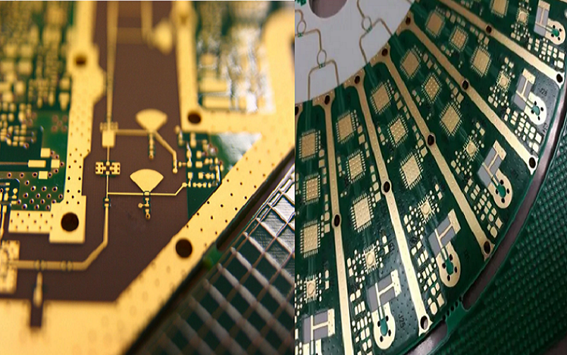
High-speed PCBs for RF and Microwave Applications
Frequency & Performance Scope
- Operating range: 6 GHz to 100 GHz for RF, microwave, and mmWave applications
- Insertion loss target: ≤0.3 dB per inch at 30 GHz
- Impedance tolerance: ±5% single-ended, ±3% differential
- Dk/Df stability: ≤±0.05 across temperature and frequency
- Compliance: IPC-2221, IPC-6012 Class 3
Critical Electrical Requirements
- Controlled impedance: 50 Ω single-ended, 85–100 Ω differential
- Intra-pair skew: ≤1 ps per inch for differential pairs
- Moisture absorption: ≤0.1% to prevent dielectric shift
- CAF resistance: ≥60 minutes at 85 °C / 85% RH
Key Considerations for High-Speed RF/Microwave PCBs
Impedance Control
- Target: 50 Ω ±2% for RF, 100 Ω ±2% for differential
- Microstrip: Dk 3.2–4.2, height 3–10 mil, width 4–12 mil
- Stripline: Dk 3.0–4.0, total dielectric 6–16 mil
- Trace tolerance: ±0.1 mil with etch compensation
Learn more about: 50Ω / 75Ω / 100Ω Impedance in High Density Interconnect (HDI) PCBs: Design & Production Guide
Hybrid Stack-ups
- RF signal layers: ultra-low-loss high frequency pcb
- Power/ground layers: high-thermal-conductivity dielectric
- Core thickness: 4–20 mil; prepreg: 2–6 mil
- Symmetric structure limits warpage to ≤0.05 inch per meter
Material Selection
Low-Loss Material Grades
- Standard Low Loss: Df 0.006–0.011 at 10 GHz, ≤6 GHz
- Enhanced Low Loss: Df 0.003–0.006 at 10 GHz, 6–30 GHz
- Ultra Low Loss: Df 0.0015–0.003 at 10 GHz, 30–100 GHz
Material Selection for High-Speed Digital & RF/Microwave Designs
| Category | Material | Tg (°C) | Dk @10GHz | Df @10GHz | Copper Rz (μm) | Application |
|---|---|---|---|---|---|---|
| Ultra-Low Loss | TerraGreen 400G2 | 200 | 3.10 | 0.0015 | ≤1.1 | 100G+, 5G mmWave, Ultra-Low Loss |
| Ultra-Low Loss | TerraGreen 400G | 200 | 3.15 | 0.0017 | ≤1.1 | High-Speed Digital, RF Hybrid |
| Ultra-Low Loss | Tachyon 100G | 215 | 3.04 | 0.0021 | ≤2.1 | 100G Backplanes, Low Skew |
| Ultra-Low Loss | Megtron 8 | 220 | 3.00 | 0.0020 | ≤1.8 | High-End Server, 112G |
| Ultra-Low Loss | RO4835 | 200 | 3.30 | 0.0022 | ≤1.5 | mmWave, Radar, High-End RF |
| Ultra-Low Loss | RO4450F | 200 | 3.50 | 0.0024 | ≤1.7 | High-Speed Digital + RF |
| Low Loss | TerraGreen 400GE | 200 | 3.29 | 0.0026 | ≤2.1 | Cost-Optimized High-Speed |
| Low Loss | I-Tera MT40 | 215 | 3.45 | 0.0031 | ≤2.5 | High-Speed Digital, Mixed Signal |
| Low Loss | Megtron 7 | 200 | 3.20 | 0.0030 | ≤2.2 | 50Gbps, Server, Switch |
| Low Loss | Megtron 6 | 200 | 3.40 | 0.0035 | ≤2.5 | 25/50Gbps, Datacom |
| Low Loss | RO4003C | 200 | 3.38 | 0.0031 | ≤2.0 | RF, Microwave, 5G |
| Low Loss | Taconic TLC | 200 | 3.20 | 0.0032 | ≤2.1 | High Frequency, Radar |
| Low Loss | FR408HR | 190 | 3.65 | 0.0095 | ≤3.0 | Mid-Loss High-Speed, Cost Effective |
| Mid Loss | I-Speed | 180 | 3.63 | 0.0060 | ≤3.0 | General High-Speed, HDI |
| Mid Loss | IS580G | 195 | 3.80 | 0.0060 | ≤2.5 | High Thermal Reliability |
| Mid Loss | 185HR | 180 | 3.88 | 0.0240 | ≤3.5 | Standard High-Reliability |
| Mid Loss | N4000-13 | 180 | 3.70 | 0.0130 | ≤3.2 | Automotive, Industrial |
| Mid Loss | N4000-15 | 180 | 3.60 | 0.0150 | ≤3.3 | Industrial, Power Board |
| High Thermal Reliability | 370HR | 180 | 3.92 | 0.0250 | ≤3.5 | High-Reliability Industrial |
| High Thermal Reliability | IS550H | 200 | 4.43 | 0.0160 | ≤3.0 | Automotive, High Voltage |
| High Thermal Reliability | N4000-29 | 200 | 4.10 | 0.0290 | ≤3.4 | EV, Inverter, Power |
| RF/Microwave Special | Astra MT77 | 200 | 3.00 | 0.0017 | ≤2.5 | 77/79GHz Radar, mmWave |
| RF/Microwave Special | RO3003 | 200 | 3.00 | 0.0013 | ≤1.8 | Satcom, Radar, 6G |
| RF/Microwave Special | RO3010 | 200 | 10.2 | 0.0022 | ≤2.0 | High-Dk RF, Filter |
| RF/Microwave Special | Taconic RF-30 | 200 | 3.00 | 0.0019 | ≤2.0 | Low-Loss Microwave |
Copper Surface Roughness
- HVLP3/VLP1: Rz ≤1.1 μm for lowest insertion loss above 20 GHz
- VLP2: Rz ≤2.1 μm for balanced performance and cost
- Standard ED: Rz ≤3.0 μm not recommended above 10 GHz
Design Considerations
Skin Effect
- Current concentrates at 0.3–1.2 μm depth from 10–100 GHz
- Smooth copper reduces loss by 15–30% compared to standard foil
- VLP1 or VLP2 foil required for all signals above 6 GHz
Thermal Management
- Thermal via pitch: ≤0.3 mm under power amplifiers
- Thermal conductivity: ≥0.8 W/m·K for dielectric materials
- Continuous operating temperature: 125 °C
- Temperature deviation: ≤±5 °C across signal paths
Manufacturing Capabilities
Precision Fabrication Parameters
- Line/space: 2/2 mil for HDI PCB, 3/3 mil for standard designs
- Microvia diameter: 50–100 μm using laser drilling
- Layer-to-layer registration: ±25 μm
- Impedance coupons included on every production panel
Surface Treatment & Plating
- ENEPIG: preferred for RF and microwave signal pads
- Immersion silver: low loss and stable at high frequencies
- Surface roughness: Ra ≤0.3 μm for all RF signal layers
- Plating uniformity: ±5% across entire panel
Top High-Frequency Material Suppliers
Rogers Corporation
- RO4000 series: Df 0.002–0.004 for RF and microwave
- RO3000 series: ceramic-filled, stable Dk over wide bandwidths
Isola
- TerraGreen series: ultra-low-loss for 100G+ digital and mmWave
- Tachyon series: low skew for high-speed backplanes
Taconic
- TLC series: Df 0.0015–0.003 for radar and satcom
- RF-30: cost-effective microwave-grade laminate
Panasonic PCB
- Megtron 6/7: low-loss laminates for hybrid digital-RF designs
- High reliability for mass-production environments
Common Applications
Industry Use Cases
- 5G/6G macro and small cells: 6 GHz–40 GHz
- Automotive radar: 24 GHz, 77 GHz, 79 GHz
- Satellite communications: C-band, Ku-band, Ka-band
- Test and measurement: 10 MHz–110 GHz systems
Product Types
- Power amplifiers and low-noise amplifiers
- Filters, couplers, and power dividers
- Antenna arrays and feed networks
- Optical transceiver RF interfaces
Case Study
Project Specifications
- Layers: 12-layer symmetric hybrid HDI PCB
- Frequency: 6–30 GHz microwave transceiver
- Materials: TerraGreen 400G + I-Tera MT40
- Impedance: 50 Ω ±2%, 100 Ω ±2%
- Copper: VLP1 ultra-smooth foil, Rz ≤1.1 μm
Issues Encountered
- Insertion loss: 0.42 dB/in at 30 GHz (over limit)
- Impedance shift: ±7% outside specification
- Warpage: 0.09 inch/m causing assembly failure
Improvements & Results
- Upgraded to VLP1 copper and tighter dielectric tolerance
- Implemented fully symmetric stack-up
- Final insertion loss: 0.26 dB/in at 30 GHz
- Impedance controlled to ±2%
- Warpage reduced to 0.04 inch/m
- Production yield improved from 71% to 94.2%
Quality Control & Compliance
Testing Protocols
- S-parameter measurement: insertion loss, return loss up to 110 GHz
- TDR impedance test: 20 ps rise time, ±1.5% resolution
- Surface roughness verification: optical profilometer
- Thermal cycle test: 1000 cycles from -55 °C to 125 °C
Standards Compliance
- IPC-2221A: generic PCB design standard
- IPC-6012 Class 3: high-reliability performance
- IPC-4103: high-frequency laminate requirements
- ISO 9001: quality management system
FAQ
Material Selection for Microwave
Microwave designs above 20 GHz require ultra-low-loss materials with Df ≤0.004 and ultra-smooth copper foil to minimize insertion loss.
Copper Roughness Requirements
VLP1 copper with Rz ≤1.1 μm is required for frequencies above 20 GHz. VLP2 with Rz ≤2.1 μm is acceptable for 6–20 GHz applications.
Impedance Standards for RF
RF and microwave PCBs follow IPC-2221 and IPC-6012. Standard impedance is 50 Ω ±2% for single-ended signals and 100 Ω ±2% for differential pairs.
If you need professional high speed PCB impedance design support or quotation, our team provides free DFM check and fast turnaround.


![Understanding PCB Costs & Pricing [Your Complete Guide]](https://hdicircuitboard.com/wp-content/uploads/elementor/thumbs/Understanding-PCB-Costs-Pricing-Your-Complete-Guide-qzzhe6mcaxuolkux3xalfktgavumi9y1aqfbs9bpv4.webp "Understanding PCB Costs & Pricing [Your Complete Guide]")


