
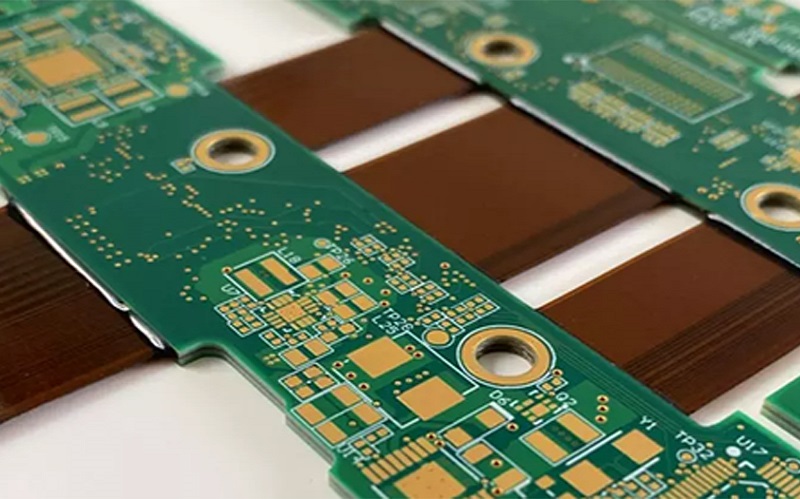
A rigid-flex PCB is an integrated circuit structure that combines rigid FR‑4 sections for component mounting and flexible polyimide regions for 3D routing and bending. Unlike separate rigid boards and cables, rigid-flex is built in a single lamination process, eliminating connectors, reducing failure points, and enabling compact, high‑reliability assemblies. Most performance and yield issues stem not from material limits, but from designs that do not follow fabrication constraints. This guide reflects actual best practices shared in professional rigid-flex design and manufacturing workshops.
Learn more about: What is a Rigid-Flex PCB? Construction, Advantages, Applications & Design Guide
Rigid-Flex PCB Construction
Layer Structure
Rigid-flex PCBs are monolithic structures, not separate rigid and flex boards bonded together.
- Rigid regions use standard FR‑4 cores and prepreg, typically 0.4 mm to 1.0 mm thick
- Flex regions use polyimide (PI) dielectric, 25 μm to 75 μm total thickness
- Flex layers are embedded within the stackup and terminate gradually into rigid sections
- No-flow prepreg is used during lamination to prevent resin contamination in flex zones
- Coverlay protects flex areas; solder mask is applied only to rigid surfaces
Transition Zone Architecture
The transition between rigid and flex is the most mechanically stressed area in the assembly.
- Transition length must be at least 5 times the flex thickness per IPC‑2223
- Abrupt layer termination causes delamination and early fatigue failure
- A tapered profile reduces stress concentration at the rigid‑flex boundary
- Components and vias must maintain clearances away from transition edges
Material Selection Guidelines
Copper Foil Types
Copper performance directly defines bending life and reliability.
- Rolled Annealed (RA) copper provides 25–30% elongation for dynamic bending
- Electrodeposited (ED) copper supports only static bending with lower cycle life
- RA copper is required for applications involving repeated motion
- ED copper may be used in fixed, non‑cycling flex sections
Dielectrics and Protective Layers
Material choice prevents cracking, peeling, and insulation failure.
- Polyimide (PI) is the standard dielectric for flex regions
- Adhesiveless stackups allow thinner constructions and tighter bend radii
- Coverlay is a flexible polyimide film used exclusively for flex protection
- Solder mask is brittle and must never be applied to bending areas
Bend Design Rules & Routing Standards
Static and Dynamic Bend Radius
Bend radius is determined by flex thickness and application type.
- Static bend (formed once during assembly): minimum 2 × flex thickness
- Dynamic bend (repeated cycling): minimum 5 × to 10 × flex thickness
- Example: 50 μm flex = 0.1 mm static radius, 0.25–0.5 mm dynamic radius
- Multilayer flex structures require proportionally larger bend radii
Trace Routing in Flex Zones
Routing direction determines mechanical stress and service life.
- Traces must run parallel to the bend axis
- Perpendicular routing increases stress by a factor of 5 and causes rapid cracking
- Curved paths are preferred over sharp angles to reduce stress points
- Solid copper planes must be replaced with hatched or mesh planes in flex areas
- Vias, pads, and components are prohibited inside bend regions
Critical Design for Manufacturing (DFM) Rules
Transition Zone Design Constraints
Strict clearances prevent fractures during manufacturing and operation.
- Minimum transition length = 5 × flex thickness
- Components must be placed at least 0.8 mm away from transition lines
- Vias near transitions require teardrop enhancement
- Asymmetric copper distribution causes warping during lamination
- Copper distribution must be balanced within ±10% across layers
Stackup Design Requirements
Symmetry and layer placement directly impact yield and reliability.
- Flex layers should be centered and symmetric within the stackup
- Unbalanced stacks cause curling, misregistration, and delamination
- Flex layers should not extend unnecessarily through rigid sections
- Maximum via aspect ratio is limited to 8:1 for reliable plating
- Laser microvias start from 75 μm; mechanical drills from 150 μm
Manufacturing Process Overview
Fabrication Sequence
Rigid-flex follows a specialized sequential manufacturing flow.
- Flex circuits are etched and prepared separately
- Coverlay is laminated onto flex regions
- Rigid innerlayers are processed and registered to flex layers
- All layers are bonded in a single vacuum lamination cycle
- Sequential laser and mechanical drilling is performed
- Plating connects rigid and flex layers electrically
- Outerlayer imaging, solder mask, and surface finish are applied
- 100% electrical testing and reliability validation are completed
Yield and Quality Realities
Production yield reflects structural complexity and design discipline.
- Standard rigid PCBs: 95–99% manufacturing yield
- Flexible circuits: 85–92% yield
- Rigid‑flex circuits: 70–85% yield
- Complex multilayer rigid‑flex designs may fall to 60–75% yield
- Prototype testing and DFM reviews reduce failure rates significantly
Common Design Failures
- Placing vias or components within bend zones
- Routing traces perpendicular to the bending axis
- Using insufficient bend radius for dynamic applications
- Applying solder mask on flexible regions
- Creating excessively short or abrupt transition zones
- Allowing unbalanced copper distribution across layers
- Neglecting teardrops on vias near rigid‑flex boundaries
- Exceeding recommended via aspect ratios
Assembly and Reliability Considerations
Component Mounting Rules
Components require stable support to avoid mechanical failure.
- Components may be placed on flex regions only with stiffeners
- Stiffener materials include FR‑4, PET, and aluminum
- Stiffened areas must remain outside dynamic bending zones
- ENIG is the preferred surface finish for flex-compatible reliability
Environmental and Mechanical Performance
Rigid-flex provides enhanced performance under harsh conditions.
- Operating temperature range: −40 °C to +125 °C
- Withstands vibration up to 20G across 10–2000 Hz
- Survives 100+ thermal shock cycles between −40 °C and 125 °C
- Reduces assembly size by 40–70% and weight by 30–60%
- Eliminates 80–100% of board-to-board connectors and failure points
Application Overview
Military & Aerospace
Rigid-flex is widely used in high-reliability flight and communication systems.
- Avionics and navigation assemblies
- Satellite sensor and communication modules
- Guidance and control systems requiring shock resistance
- Systems governed by AS9100 and IPC Class 3 standards
Medical Devices
Medical designs benefit from miniaturization and long-term stability.
- Portable diagnostic and monitoring equipment
- Surgical and endoscopic tooling
- Wearable health sensors
- Applications requiring ISO and regulatory compliance
Consumer Electronics
Compact devices use rigid-flex for space efficiency and durability.
- Smartphone and foldable device internal interconnects
- Wearable devices and hearables
- Laptop hinge and camera modules
- Compact audio and imaging equipment
Technical Parameters (IPC‑2223 & IPC‑6013)
- Minimum line width and spacing: 30 μm / 30 μm (rigid), 20 μm / 20 μm (flex)
- Minimum flex bend radius: 2 × thickness (static), 5–10 × thickness (dynamic)
- Transition zone length: minimum 5 × flex thickness
- Component clearance from transition: ≥ 0.8 mm
- Copper distribution balance: ±10% layer-to-layer
- Operating temperature: −40 °C to +125 °C
- Via aspect ratio: maximum 8:1
- Impedance tolerance: ±6% for controlled impedance designs
Frequently Asked Questions
Q1: Can components be mounted directly on flexible PCB areas?
A1: Components may be mounted on flex sections only if supported by stiffeners such as FR‑4 or PET. All mounted areas must remain outside bending zones.
Q2: What is the minimum bend radius for a rigid-flex PCB?
A2: Per IPC‑2223, static bends require a minimum radius of 2 times the flex thickness. Dynamic bending requires 5 to 10 times the flex thickness.
Q3: Why is solder mask not used on flexible regions?
A3: Solder mask is brittle and will crack under bending stress. Polyimide coverlay is the only acceptable protective material for flex circuits.
Q4: How can I improve rigid-flex PCB production yield?
A4: Improve yield by following transition rules, balancing copper distribution, avoiding vias in bends, using appropriate bend radii, and completing a DFM review before manufacturing.
If you need professional rigid flex PCB design support or quotation, our team provides free DFM check and fast turnaround.


![Understanding PCB Costs & Pricing [Your Complete Guide]](https://hdicircuitboard.com/wp-content/uploads/elementor/thumbs/Understanding-PCB-Costs-Pricing-Your-Complete-Guide-qzzhe6mcaxuolkux3xalfktgavumi9y1aqfbs9bpv4.webp "Understanding PCB Costs & Pricing [Your Complete Guide]")


