
A flexible PCB relies on engineered substrate, conductor, and protective materials to enable bending, miniaturization, and reliable electrical performance. This guide evaluates polyimide (PI) and liquid crystal polymer (LCP) as the two dominant substrate technologies, covering conductive layers, coverlay, adhesives, stiffeners, and adhesiveless structures. Factory-verified parameters, IPC design standards, real fabrication cases, and quality control protocols are provided to support material selection for bendable circuit board and rigid flex PCB applications, balancing mechanical flexibility, high-frequency performance, thermal stability, and production yield.
Learn more about: What is a Flexible PCB? A Complete Guide for Beginners
Flexible PCB Materials
Material System Fundamentals
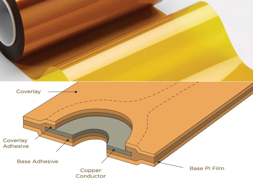
A flexible printed circuit board consists of a layered composite structure designed to maintain electrical function under repeated or static bending. Each material layer is specified to dimensional and performance standards defined in IPC-4101, IPC-6013, and IPC-2223.
- Substrates provide dielectric isolation and mechanical flexibility
- Conductive layers enable signal transmission and power delivery
- Protective layers prevent physical damage and environmental contamination
- Bonding materials ensure layer adhesion without sacrificing flexibility
- Reinforcement materials support component mounting in high-stress regions
Material-Driven Performance Attributes
Material selection directly defines functional limits for a flexible pcb board, including bend life, operating temperature, signal integrity, and environmental resistance.
- Bend cycle performance ranges from 10,000 to over 1,000,000 cycles
- Dielectric constant (Dk) varies from 2.9 to 4.5 across substrate types
- Continuous operating temperature spans from -40°C to +180°C
- Moisture absorption ranges from 0.02% to 3.0%
- Minimum feature size supports 20μm/20μm line and space for high-density designs
Key Flexible PCB Material Components
Substrate and Conductive Layer Architecture
The substrate and conductive foil form the core structure of every flexible printed circuit, with thickness and material type defining mechanical behavior.
- Substrate thickness options: 25μm, 50μm, 75μm, 125μm
- Copper foil thickness: 12μm, 18μm, 35μm
- Minimum bend radius: 2× substrate thickness (static), 5–10× (dynamic)
- Impedance tolerance: ±6% for controlled-impedance flexible circuit designs
Secondary Functional Materials
Auxiliary materials preserve reliability during assembly and field operation while maintaining the bendable characteristics of the assembly.
- Coverlay films protect conductors in dynamic flex regions
- Adhesives bond layers while accommodating mechanical strain
- Stiffeners reinforce areas supporting surface-mounted components
- Adhesiveless constructions reduce total thickness and improve fatigue resistance
Polyimide Substrates
Material Composition and Thermal Properties
Polyimide (PI) is the industry-standard substrate for flexible PCB assemblies, offering exceptional thermal stability and mechanical toughness.
- Glass transition temperature (Tg): 280–340°C
- Continuous operating temperature: -40°C to +180°C
- Moisture absorption: 2.0–3.0% at 85°C/85%RH
- Tensile strength: 200–250 MPa
Electrical and Mechanical Behavior
Polyimide provides balanced electrical isolation and flexibility suitable for most industrial, medical, and consumer applications.
- Dielectric constant (Dk): 3.4–4.5 at 1GHz
- Dissipation factor (Df): 0.008–0.010 at 1GHz
- Bend life exceeds 1,000,000 cycles with rolled-annealed copper
- Compatibility with standard lamination and etching processes
LCP Substrates
Molecular Structure and Stability
Liquid crystal polymer (LCP) is a high-performance thermoplastic substrate engineered for low-loss signal transmission and near-zero moisture absorption.
- Glass transition temperature (Tg): 210–280°C
- Continuous operating temperature: -40°C to +150°C
- Moisture absorption: 0.02% at 85°C/85%RH
- Low coefficient of thermal expansion (CTE): 10–15 ppm/°C
High-Frequency Electrical Performance
LCP substrates deliver superior signal integrity for high-speed and millimeter-wave flexible PCB applications.
- Dielectric constant (Dk): 2.9–3.2 stable across 1–20GHz
- Dissipation factor (Df): 0.001–0.004 at 1–10GHz
- Minimal signal drift under temperature and humidity variation
- Excellent impedance control for 5G and radar applications
Conductive Layer
Rolled-Annealed (RA) Copper
Rolled-annealed copper foil is the preferred conductor for dynamic flexible printed circuit applications due to its enhanced ductility.
- Elongation rate: 25–30%
- Bend cycle life: 10× greater than electrodeposited (ED) copper
- Recommended thickness: 12μm and 18μm for flex zones
- Supports minimum bend radius down to 2× substrate thickness
Thickness Specifications
Copper thickness directly impacts current-carrying capacity and mechanical flexibility in a bendable circuit board.
- 12μm (1/3 oz): for high-density, low-current signal paths
- 18μm (1/2 oz): general-purpose flexible PCB designs
- 35μm (1 oz): power circuits limited to static bending regions
- Current capacity: 0.5–3.0A per 100μm trace width based on thickness
Coverlay
Protective Film Function and Specifications
Coverlay is a flexible insulating film applied to flex regions to protect conductors from physical damage and short circuits.
- Material: polyimide film, 25–50μm thickness
- Bonding adhesive: 15–25μm acrylic layer
- Coverage margin: minimum 0.5mm over conductor edges
- Laser-cut accuracy: ±25μm for fine-feature flexible pcb board designs
Application Best Practices
Coverlay application follows strict manufacturing rules to avoid delamination and cracking during bending.
- Full coverage over all dynamic flex traces
- No overlap onto component pads without precision cutouts
- Exclusion of solder mask from flex bending zones
- Lamination at 160–180°C under controlled pressure
Adhesives
Bonding Material Types
Adhesives join substrate layers and coverlay while maintaining mechanical compliance in a flexible PCB.
- Acrylic adhesives: high flexibility, ideal for dynamic bending
- Epoxy adhesives: high thermal resistance for static applications
- Thickness range: 15–25μm for standard flex constructions
- Temperature resistance: -40°C to +125°C for acrylic systems
Adhesiveless Polyimide
Adhesiveless polyimide structures eliminate adhesive layers to reduce thickness and improve bending performance.
- Total stack thickness reduced by 15–25μm
- Improved bend fatigue life and minimal stress accumulation
- Higher manufacturing cost requiring specialized lamination
- Preferred for high-density rigid flex PCB and wearable devices
Stiffeners
Reinforcement Material Options
Stiffeners provide mechanical support for component mounting on flexible circuit board sections.
- FR-4: 0.2–1.0mm thickness for general use
- PET: 0.1–0.5mm thickness for lightweight applications
- Aluminum: 0.3–1.0mm thickness for high-power components
- Placement restricted to non-bending regions per IPC-2223
Design and Assembly Constraints
Stiffener placement follows strict rules to avoid stress concentrations and assembly defects.
- Minimum 1mm clearance from bend lines
- Minimum 0.8mm clearance from rigid-flex transition zones
- Thickness matching to adjacent rigid sections reduces warpage
- Removable adhesive allows rework during prototype assembly
Polyimide (PI) – The Industry Standard
Key Characteristics
Polyimide exhibits thermal stability, mechanical toughness, and broad manufacturing compatibility.
- High thermal resistance up to 180°C continuous operation
- Excellent chemical and solvent resistance
- Superior flex fatigue life with RA copper conductors
- Wide thickness availability from 25μm to 125μm
Best Applications
PI is the optimal choice for most general and high-reliability flexible PCB applications.
- Medical devices and diagnostic equipment
- Industrial controls and aerospace assemblies
- Wearable electronics and portable instrumentation
- Consumer devices requiring repeated mechanical bending
Advantages
- Mature manufacturing process with high production yield
- Excellent mechanical flexibility and fatigue resistance
- Broad material thickness and supplier availability
- Compliance with IPC-6013 Class 3 performance standards
Limitations
- Higher moisture absorption affecting high-humidity performance
- Higher dissipation factor limiting ultra-high-frequency use
- Increased brittleness at extreme low temperatures
- Requires pre-baking at 125°C for 4 hours to prevent delamination
Liquid Crystal Polymer (LCP) – The High-Frequency Alternative
Key Characteristics
LCP provides stable electrical properties and minimal moisture absorption for demanding high-speed applications.
- Ultra-low dissipation factor across millimeter-wave frequencies
- Near-constant dielectric constant over wide frequency ranges
- Near-zero moisture absorption for stable outdoor performance
- Low CTE matching copper for reduced thermal stress
Best Applications
LCP is engineered for high-frequency and high-humidity flexible printed circuit applications.
- 5G communication modules and radar systems
- High-speed data interfaces and RF flexible PCB assemblies
- Outdoor and automotive sensors
- Millimeter-wave wearable and portable devices
Advantages
- Exceptional high-frequency signal integrity with low loss
- Stable electrical performance across temperature and humidity
- Hermetic barrier properties preventing moisture ingress
- Compatibility with lead-free reflow soldering up to 260°C
Limitations
- Higher material cost compared to standard polyimide
- Limited substrate thickness options (12.5–50μm)
- Reduced thermal resistance relative to polyimide
- Requires plasma treatment for reliable coverlay adhesion
Comparison Table: PI vs. LCP
| Parameter | Polyimide (PI) | Liquid Crystal Polymer (LCP) | Performance Impact |
|---|---|---|---|
| Dielectric Constant (Dk) | 3.4–4.5 @ 1GHz | 2.9–3.2 @ 1–20GHz | LCP supports more consistent high-speed impedance |
| Dissipation Factor (Df) | 0.008–0.010 | 0.001–0.004 | LCP reduces signal loss by 50–75% at high frequencies |
| Moisture Absorption | 2.0–3.0% | 0.02% | LCP maintains stability in high-humidity environments |
| Continuous Temperature | -40°C to +180°C | -40°C to +150°C | PI supports higher-temperature industrial environments |
| Bend Cycle Life | >1,000,000 | >500,000 | PI offers improved long-term dynamic flex performance |
| Relative Cost | 1.0x | 3.0–5.0x | PI is economical for high-volume consumer designs |
| IPC Standard | IPC-6013 Class 3 | IPC-6013 Class 3 | Both qualify for high-reliability flexible PCB applications |
Selection Summary
Substrate Selection Criteria
Material choice is determined by operating frequency, environmental conditions, mechanical requirements, and cost targets.
- Select PI for general flex, high-temperature, and high-dynamic-bend applications
- Select LCP for high-frequency, low-loss, and high-humidity deployments
- Use RA copper in all dynamic flex zones regardless of substrate
- Implement adhesiveless designs for ultra-thin rigid flex PCB applications
Learn more about: What is a Flexible Circuit Board? A Complete Guide for Beginners
Core Technical Parameters
- Minimum line/space: 20μm/20μm (IPC-6013 Class 3)
- Minimum laser via diameter: 75μm
- Aspect ratio: maximum 8:1 for reliable plating
- Impedance tolerance: ±6% per IPC-2221
- Bend radius: 2× thickness (static), 5–10× (dynamic)
- Transition zone length: ≥5× flex thickness (IPC-2223)
Case Study
Project Overview
A 6-layer rigid flex PCB for a portable medical monitor used 25μm PI flex sections with 18μm RA copper, 0.4mm rigid FR-4 regions, and acrylic adhesive layers. Targets included 100,000+ bend cycles and 90% production yield.
Initial Challenges
- Delamination at coverlay edges due to inadequate pre-baking
- Copper cracking in dynamic bend zones from 90° trace routing
- Excessive moisture absorption causing impedance drift
- Production yield limited to 76% from lamination defects
Process Improvements
- Implemented 125°C, 4-hour pre-baking to reduce moisture content
- Revised trace routing parallel to bend axis with curved transitions
- Replaced standard adhesive with adhesiveless PI structure
- Added 0.5mm coverlay overlap and precision laser cutting
Final Results
- Bend cycle life increased to 180,000 cycles
- Impedance stability maintained within ±6% tolerance
- Production yield improved to 88%
- Field failure rate reduced from 2.1% to 0.2% annually
Common Design Errors
Substrate and Material Misapplication
- Using LCP in high-temperature industrial environments exceeding 150°C
- Applying solder mask directly onto flex bending regions
- Selecting ED copper for dynamic flex applications
- Insufficient pre-baking of polyimide before lamination
Mechanical and Geometric Violations
- Routing traces perpendicular to bend direction
- Placing vias and components within flex bend zones
- Using bend radius below 2× substrate thickness
- Inadequate transition length less than 5× flex thickness
Assembly and Stackup Mistakes
- Unbalanced copper distribution causing warpage
- Missing stiffeners under surface-mounted components
- Excessive adhesive thickness reducing flexibility
- Inadequate coverlay margin leading to insulation failure
Quality Control Requirements
Mechanical and Environmental Testing
- Dynamic bend testing: 10,000–100,000 cycles per IPC-6013
- Thermal shock testing: 100 cycles between -40°C and 125°C
- Pressure cooker testing: 2 hours at 121°C to evaluate delamination
- Peel strength testing for coverlay and adhesive bond integrity
Electrical Quality Verification
- 100% electrical continuity and isolation testing
- TDR impedance measurement with ±6% tolerance
- Surface insulation resistance testing exceeding 10¹⁴Ω/square
- X-ray inspection for via plating quality and layer registration
Frequently Asked Questions
Q1: Which substrate is better for dynamic bending applications?
A1: Polyimide (PI) is superior for dynamic bending due to higher flex fatigue life, broader thickness availability, and better manufacturing compatibility compared to LCP.
Q2: When should LCP be used instead of polyimide in a flexible PCB?
A2: LCP is preferred for high-frequency applications above 5GHz, outdoor environments, and designs requiring stable electrical performance with near-zero moisture absorption.
Q3: What is the difference between PCB and PCA in flexible circuit assembly?
A3: A flexible PCB is the bare circuit substrate, while a PCA (printed circuit assembly) includes soldered components, connectors, and stiffeners applied to the flexible board.
Q4: Can adhesiveless polyimide be used in rigid flex PCB designs?
A4: Yes, adhesiveless polyimide is widely used in rigid flex PCB constructions to reduce total thickness, improve bend reliability, and minimize delamination risks in high-reliability applications.
If you need professional flexible PCB design support or quotation, our team provides free DFM check and fast turnaround.


![Understanding PCB Costs & Pricing [Your Complete Guide]](https://hdicircuitboard.com/wp-content/uploads/elementor/thumbs/Understanding-PCB-Costs-Pricing-Your-Complete-Guide-qzzhe6mcaxuolkux3xalfktgavumi9y1aqfbs9bpv4.webp "Understanding PCB Costs & Pricing [Your Complete Guide]")


